Electrical System
Lights and Signals
Headlamp
The FST Platform headlamp varies by model.
Both are LED-based and are proprietary designs by Zero.
Headlamp
The SRF Model headlamp is LED-based, seemingly proprietary.
- The headlamp assembly is sealed, so changing the LEDs is not supported.
- The headlamp angle adjustment screw tilts the entire assembly as one unit.
- There is a noticeable gap between the high beam and low beam light spread.
References
Headlamp
The SRS Model headlamp is LED-based, seemingly proprietary.
- There are four cells in a horizontal row; the LEDs seem to aim downwards from above, with a special optical reflector to create the forward beam spread.
Mounting
- It appears that this assembly bolts to a model-specific frame extension of the head tube.
Removal
Servicing
- The unit is self-contained and not designed to be serviceable, but there are affordances in it that might allow some work.
Turn Signals
Zero uses a triangle-shaped turn signal housing on a flexible stalk.
The turn signals are oriented so the front and rear are interchangeable if you swap sides going from front to rear and vice versa.
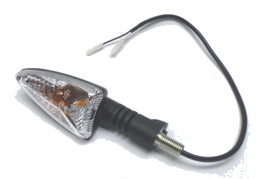 Left-hand front (right-hand rear) turn signal |
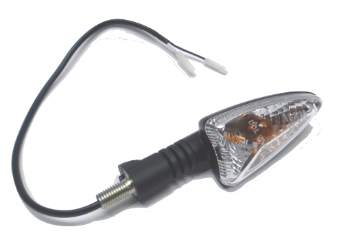 Right-hand front (left-hand rear) turn signal |
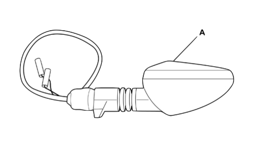 Turn signal drawing |
Maintenance
Always check for functioning turn signals (running light, headlamp, turn signals, brakes).
Connectors
Threaded insert into the headlamp and tail bracketing (not identified, could be M8) with a notch to hold their position.
Barrel-style single wire Molex connectors (2 per signal):
- 1 Pin Molex .062 Female Plug Connector w/Pins 03-06-1011
- 1 Pin Molex .062 Male Plug Connector w/Pins 03-06-2011
Turn Signal Bulbs
2013+ (Gen2, Gen3?)
Type PY10W, similar to 1156, but the side pins are offset by 150 degrees rather than 180.
Also called BAU15S or R10W.
The glass is amber (as the lenses are clear) and smaller, since the regular 1156 glass is too big.
AF1 Racing references #AP8127489 as "amber turn signal bulb, staggered pins"
2009-2012 (Gen1)
Clear 1156 incandescent bulbs, very standard.
Turn Signal Flasher
The turn signal ("blinker") flasher is a simple three prong flasher relay.
It's attached directly by a plug so is easily replaced if it fails (or for an LED compatible unit).
Label
Flasher Unit 12V
2x10W
PN: 8078
Made by Ecie Cheng Du
or
GUILERA
Flasher Unit 12V
10+10W+1,2W
P.N. 013341
Low Noise Revision
As of 2016, the part is revised with the description "low noise".
This suggests reduced electronic and/or audible noise.
This model of flasher relay is noticeably quieter, and that year coincides with reports from Zero management of EU EMF/EMC noise compliance expenditures.
Silent Revision
As of 2020?, the part is from the manufacturer Guilera and makes no audible noise.
This again suggests reduced electronic noise, again likely as a result of EU EMF/EMC noise compliance expenditures.
Wiring
The orientation is specific. Reversing the (+) and (-) wiring may be necessary if you buy the wrong orientation of relay.
Look at the pins with the middle L (center)(Load) pin on top and the B and E below it to each side.
- 2018+: The orientation should be E (-) (left), L (center/top), then B (+) (right).
Ref. report from a 2019S owner
This orientation is know as a CF14 relay per pacificcricket - 2013-2017:
The orientation should be B (+) (left), L (center/top), then E (-) (right)
This orientation is know as a CF13 relay
| Years | Platform | Location | Photo |
|---|---|---|---|
| 2012 | S/X | Under the seat below the fuse block. | 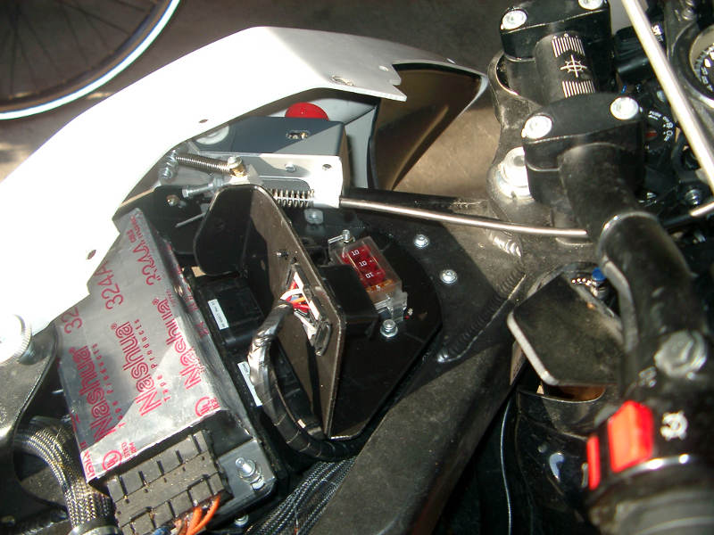 |
| 2013+ | X | Behind the right fairing | 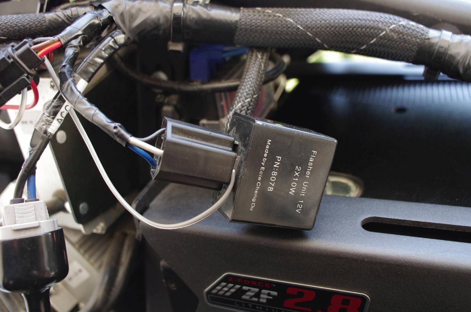 |
| 〃 | S | In front of the front plastics area under the frame "wishbone" with other electrical connections. | 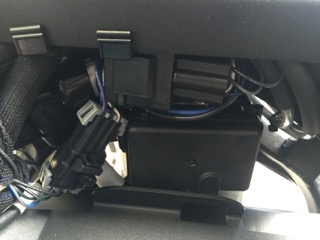 |
Turn Signal Flasher Replacement
FST Platform/Turn Signal Flasher Replacement
Tail Light
The tail light enclosure includes the rear running and brake lights.
The lights inside are LEDs.
The assembly is made by TRIOM, an Italian company.
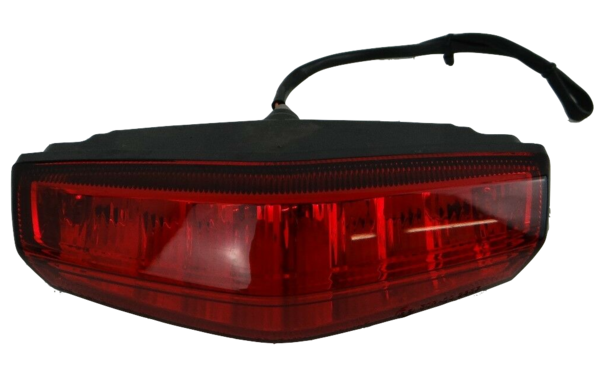 Tail Light (rear)
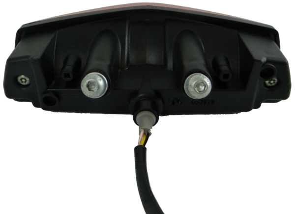 Tail Light (front)
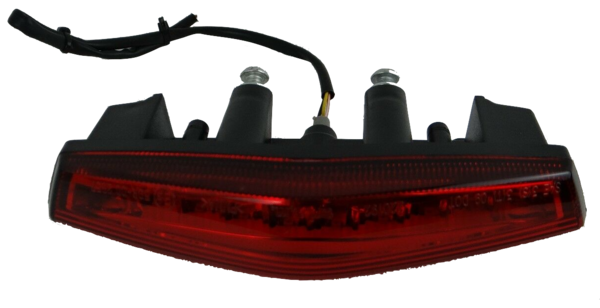 Tail Light (top)
The product made for Zero has not been identified so far, but has shown no failures, either.
Horn
The horn is a K70-H Electromagnetic Disc Horn, P/N 45-06774 for model years 2014-2020.
| Current | 1.5A @ 13V |
| Sound Level | 109dB @ 2m |
| Pitch | 430Hz |
| Weight | 155g |
Switchgear
Fuse Block
The 12V fuse block protects the DC-DC 12V Converter from faults in all the 12V components on Gen2 models.
Gen3 models have a fuse block but the protection has redundant upstream components in the MBB, so the fuse block just helps with isolation.
| Platforms | Years | Components | Rating | Notes | Photo |
|---|---|---|---|---|---|
| S,X | 2013+ | Accessory circuit | 10A | Sumimoto plug (all years) and SAE plug (2014+ years) | 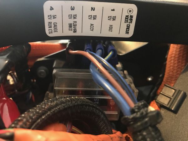 2013 Fuse Block |
| 〃 | 〃 | Headlamp | 10A | 〃 | |
| 〃 | 〃 | Instrument cluster (Dash) running lights |
5A | 〃 | |
| 〃 | 〃 | Turn signals (Flashers) horn brake lights |
10A | 〃 | |
| 〃 | 〃 | Ignition key | 5A | 〃 | |
| 〃 | 2015+ | ABS circuit and the ignition key | 5A | 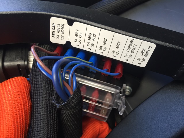 2015-2016 Fuse block (label inaccurate; rotated 180°) |
|
| 〃 | 〃 | ABS pump | 25A | limited duty | 〃 |
| 〃 | 〃 | ABS valve | 10A | 〃 |
Wiring
The fuse block connects to the positive side of the DC-DC 12V Converter output on its left side.
The downstream wires enter a mesh sleeve, through a ferrite ring to clean up RF interference, and lead forward into a larger sleeve that runs (for the S-Platform) along the left side of the forward tank area.
Location (SDS Platform)
Under the seat under the Y-shaped frame join piece's left rear leg.
For 2015+ models, the 25A ABS pump fuse is mounted to the back of the block and may require removing the frame join piece to access fully.
Location (XMX Platform)
On the frame under the right side front body panel.
For 2015+ models, the 25A ABS pump fuse is mounted to the frame above the block.
Location (FST Platform)
Under the rider's seat on the right side.
Ignition Switch
The Ignition switch is a locked turn-key operation for enabling the bike with a reasonable amount of physical security.
The switch is operated by the Ignition Lock.
Location
Through the center of the upper tripleclamp, ahead of the steering stem and handlebars and below the dash.
Routing
The ignition wiring runs under the steering head to the MBB. This implies that the MBB is at least partially powered while the bike is keyed off.
Security
Position the steering in the locked position to prevent easy access to the wiring which facilitates theft/override via "hotwiring".
Connections
MBB pins (per 2013 trace)
- 4 - Orange/White 20AWG
- 5 - Orange/Black 20AWG
Handlebar Switch Housing
The handlebar switch housing assemblies seem generic but have Torx T22 security bolt fasteners making inspection and maintenance more difficult than average.
Kill Switch
The kill switch (or engine cutoff/cutout switch) is a toggle switch on the right handlebar switch assembly prevents motor operation as a separate control from other interlocks.
Mounting
On the right handlebar switch assembly.
Operation
Push up/forward to cutoff motor operation.
Push down to enable motor operation.
When to Cutoff Motor Operation
- Whenever the bike should not be operating.
This is a redundant safety mechanism to prevent injury or damage. - If the vehicle is on its side after a crash or other incident.
This prevents spinning up the wheel. - Whenever someone unfamiliar with the motorcycle is sitting on it or nearby.
If they intentionally or unintentionally touch the throttle, this prevents their lack of familiarity from causing a surprise excursion.
Troubleshooting
The status command in the MBB console can report its reading.
While energized, a voltmeter will indicate 5V across the input leads if the switch is open, and 0V if shut.
While de-energized (and confirmed), resistance across the switch will be high if open, and low if shut.
Connections (Gen2)
It is wired as a digital input to the MBB.
SPST where the off position is an open circuit, for failsafe considerations.
Red 20AWG - (assumed high/positive-5V) to MBB pin 23 (per 2013 trace)
White 20AWG - (assumed low/0V) to MBB pin 24 (per 2013 trace)
Kickstand Switch
The Kickstand has a safety cutout switch (really a sensor) to prevent motor operation while at rest.
 Warning: |
Kickstand Sensor Electrical Equipment Hazard The connector is three pronged and needs to be connected correctly or can damage the MBB irreparably. Do not disconnect or reconnect while the vehicle is keyed on or contactor is shut to be safe. Do not short any wires together to bypass. This is a Hall effect sensor usually containing or using sensitive measurement IC's and therefore not a simple switch. |
Part
From observation, the Asahi Denso CE122 proximity sensor appears to be the part match, also used on some Triumph and KTM motorcycle models.
From the 2016 SR's sensor to its connector, the wires are Blue, Pinkish Red, and Black.
While the bike is keyed on and contactor is closed, Blue measures a stable 5V, Red measures ~2.7V and varies (need to scope this), and black appears to be a signal ground/input (needs verification when I'm not tired).
Some KTM riders with the Asahi Denso CE122 sensor have reported success using commercial bypass kits.
- Reportedly, a KTM sidestand switch bypass kit can work on a Zero without issues.
One such user suggested these are merely a potted 2.2kOhm resistor between the Red and Black wires (link here).
Zero motorcycles can be far more sensitive to faults on signalling pins so this should not be attempted unless you absolutely know what you are doing, and are willing to risk having to replace your MBB.
talonreaper has had luck on a 2016 SR with a 2.7kOhm resistor between the red and black kickstand sensor's wires to get home from being stranded in an emergency.
This is still not advised.
North or South pole magnetism activation? TODO
Connector
The connector appears to be a Sumimoto MT sealed series connector MT-3S-2, p/n 6180-3241.
Ref. Corsa Technic reference page for 6180-3241
This connector appears to be a very standard application for Japanese motorcycle interlock sensors for sidestands/kickstands.
Troubleshooting
Raise the kickstand for testing only with the rear wheel lifted off the ground via a stand or lift.
The status command in the MBB console can report its reading.
Maintenance
An unconfirmed suggestion per this Side stand safety switch discussion on EMF:
Since I was worried about the condition of my side stand safety switch and never having looked at it before, I got on my hands and knees under the bike and checked it out.
I noticed that there were a couple of wires that went into a plastic sheath that protects the wires and their connections within the switch housing from damage.
But I also noticed that the sheath's opening faces forward and it seemed like water and muck could be forced into the opening and perhaps short out the switch contacts under extreme conditions.
So what I did was to squirt some silicone sealant into the opening and sealed it off.
Hopefully, that will eliminate any possibility of water getting into the switch when riding on wet streets.
Bypass
If there is a compelling justification worth risking warranty damage, the sensor interlock preventing operating the powertrain may be bypassed.
The bypass should be performed via MBB settings configuration.
| Pin # | Wire Color | Wire Gauge |
|---|---|---|
| 10 | Yellow/Black | 20AWG |
| 11 | Orange/Black | 20AWG |
| 27 | Red | 20AWG |
Removal
Replacement
See Kickstand Switch Replacement
Tail Wiring
FST Platform/Tail Wiring
Schematic
FST Platform/Schematic
OBD-II Port
Zero models all have an OBD-II port that is reasonably accessible for troubleshooting, diagnostics, and data collection.
Its wiring is non-standard; to connect, we offer the following references:
- How to build a cable to access the MBB for how to build a cable to work with it.
- The aftermarket section on OBD-II solutions.
OBD-II Port Location
| Platform | Years | Photo | |
|---|---|---|---|
| S | 2011-2012 | In the tank area facing the forward frame join where the fuse block sits. | |
| SDS | 2013 | Above and behind the motor next to the accessory charging port, on the left-hand side. | difficult to photograph |
| 〃 | 2014-2015 | Above and behind the motor next to the accessory charging port, on the right-hand side. | difficult to photograph |
| 〃 | 2016+ | Under the seat on the left side just behind frame bulkhead that the tank plastics rest on for 2016 models. | 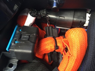 |
| XMX | 2011+ | Under the left side tank plastics. | 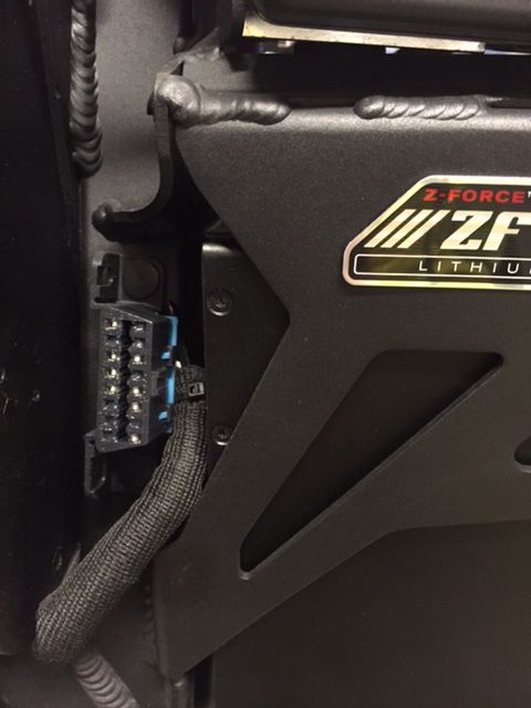 |
| FST | 2020+ | Inside the tank storage compartment |
Routing
FST Platform/Electrical Routing
Source: zeromanual.com/wiki/FST_Platform/Unofficial_Service_Manual · Wayback capture of 2025-05-17 · wiki last edited 2 May 2020 00:04. Community-written content from the Unofficial Zero Manual, reproduced for preservation; not written or verified by OpenZero. Links to pages that were not mirrored go to the Wayback Machine.