Powertrain
The powertrain includes all of Zero's power storage and delivery components including the battery, but this section focuses on the motor, power delivery via the controller, and their inputs via throttle and drive mode configurations.
Licensing
- For a time, Zero openly offered powertrain components in a licensed manner for prototyping and other uses.
- Currently, probably for reasons of liability and support overhead, this is not publicly offered but does seem available on request for companies wanting to develop products where Zero's powertrain is a good fit.
- See Zero's Z-Force Powertrain Solutions page which has a contact form.
Throttle
The Zero throttle is a very straightforward twist-grip motorcycle control that operates a sensor instead of pulling on a mechanical cable or operating hydraulics.
Zero switched the throttle supplier from a Magura with a linear potentiometer to a Bitron with a Hall-effect sensor in 2015 which changed how the wiring works.
Connections
The Zero throttle connects directly to the controller, so anything you do related to the throttle signal can compromise the operation of the bike if there's an electrical fault or discrepancy.
Example: [Sudden braking followed by no motor/throttle response on highway2016 FXS]
Customization
See Drive Modes to customize throttle input interpretation as an owner.
Use the mode control for "Custom" mode on 2014+ or "Eco" on earlier models to set the maximum torque the throttle applies.
This also directly changes how quickly torque ramps up for a given throttle twist/position.
Advanced Customization
The Sevcon motor controller settings are where most of the throttle interpretation happens.
Replacement
TODO...
Assembly
The return spring cannot be tensioned while disassembled throttle is on the handlebar. Throttle must be removed to place the spring end correctly. see video from Harlan Flagg: https://www.facebook.com/harlanflagg/videos/1364143910276196/
Troubleshooting
One report of a "snatchy" throttle turned out to have this explanation:
There is a black adjusting screw which holds the pinion gear of the throttle in place or for adjustment.
The pinion gear had moved to the right and caused the spring clip for throttle return to pop out of the slot.
This was clicking through the gears and causing a notchy throttle feel.
Resolution: Reset the pinion location and tighten the screw.
Bitron Throttle
2015+ models use a new HAL-based (Hall-effect active device) sensor from Bitron which can't be replaced easily by Domino or similar
Product reference: Bitron HAL-based throttle
Connectors
8 wire output, bundled into two pairs of 3 wires for potentiometer outputs.
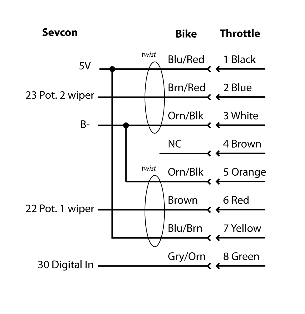
The hall-effect sensor may be a potentiometer wired up as a voltage divider as follows:
| Wire | Twist | Voltage |
|---|---|---|
| Brown | None | 0.5 |
| 〃 | Full | 4.5 |
| Brown/Red | None | 4.5 |
| 〃 | Full | 0.5 |
Regen
FST Platform/Regen
Drive Modes
The Zero platform has always offered a simple control for switching throttle and regen mappings through MBB-Sevcon interaction.
Gen1 (2009-2013)
- Through 2013, only Eco and Sport modes were available, where Eco was the customizable mode but had the Eco default as listed below.
- The modes are selected with a rocker switch on the left part of the steering head bracket forward from the handlebars.
Gen2 (2014-)
- 2014 models introduced a separate Custom mode and made Eco mode fixed.
- Modes are selected by pressing a selector button on the right hand switch assembly; the selected mode then activates when the throttle is released for a couple of seconds.
- The SRF Model introduced "Street, Sport, Eco, Rain and up to 10 programmable custom modes".
- Custom traction control modes were also introduced.
| Mode | Max Speed | Max Torque | Max Regen | Max Regen Brake |
|---|---|---|---|---|
| Eco | 70 mph | 40% | 66% | 100% |
| Custom | 70 mph | 100% | 40% | 66% |
| Sport | 98 mph | 100% | 40%? | 66%? |
Gen2 Customization
Many riders make their own Custom mode settings. There are many options that all involve tradeoffs.
- 0% (-20%) Max Regen
This enables a "coasting" mode which is very efficient, in allowing the rider to let the bike's momentum carry it forward for a while.
This also helps transition the bike from accelerating to decelerating, since the regen levels come on in a step-wise fashion, which minimizes the dive on the suspension by providing an intermediate step.
NOTE: This has one disadvantage at 0%: in extremely low traction scenarios, this can lead to dangerous fishtailing where the rear wheel starts to slip, in that it can be very difficult to slow it down. - 100% Max Brake Regen
Most riders seem to leave this setting at 100% in order to get the most out of their rear brake. - Lower Top Speed (60 or 70mph, say)
This creates a "poor man's" cruise control, where the throttle has no effect at the top end, only ensuring that a specific speed is met.
This can be useful when trying to get a maximum or ensured amount of range. - Lower Max Torque (30% or less)
This can be useful in wet or reduced traction conditions.
Torque setting is mostly about the torque ramp rate (how much torque achieved with a given amount of throttle twist).
By reducing the ramp rate, the onset of a loss of traction is much easier to control and recover from.
Most riders just switch to Eco mode in the rain, but using Custom mode for this can also be effective.
Motor
All of Zero's motors are air-cooled and mounted on a shaft that is aligned with the front pivot of the swingarm so that transmission tension is perfectly aligned with swingarm movement.
| Gen | Brand | Designation | Years | Models |
|---|---|---|---|---|
| Gen1 | Agni/Saietta | 95-R alt | 2009-2011 | S/DS/X/MX |
| 〃 | Motenergy | ME0810 | 2011-2012 | X/MX |
| 〃 | 〃 | ME0913 | 2012 | S/DS |
| Gen2 | Z-Force Motor | 75-5 | 2013 | FX/MX/XU |
| 〃 | 〃 | 〃 | 2014-2015 | FX |
| 〃 | 〃 | 〃 | 2016 | FX/FXS |
| 〃 | 〃 | 75-7 | 2013-2016 | S/DS/MMX |
| 〃 | 〃 | 75-7R | 2014-2015 | SR |
| 〃 | 〃 | 75-7R (IPM) | 2016-present | SR/DSR |
| 〃 | 〃 | 75-5 (IPM) | 2017-present | FX/FXS/S/DS (Longbrick) |
| Gen3 | 〃 | 75-10 (IPM) | 2020-present | SRF/SRS |
Z-Force Motor
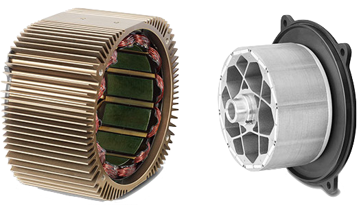

For the 2013+ models (Gen2 and Gen3), Zero has their own motor design, trademarked "Z-Force".
Features
- Sealed
- Air-cooled (via finned casing)
- Brushless
- Permanent-magnet rotor
Operation
It is a 3-phase brushless DC (BLDC) electric motor which is roughly described as a permanent magnet AC synchronous (PMAC) motor since the controller is continuously adjusting the phase angle of the field to the rotor's current position and speed.
The field must apply synchronously to the rotor, so the calibration between the position sensor and the controller is critical for efficiency, minimizing wear on the bearings, and minimizing heating of the windings and magnets.
Motenergy's Clone
Motenergy makes an unlicensed generic derivative, the ME1507, of the same form factor, rated for much lower outputs and seems to differ from Zero's motor in key ways.
From Motenergy's ME1507 product page, it's clear that they're advertising a model on par with the 2016 IPM update:
The ME1507 is an Radial Air Gap, Permanent Magnet Synchronous Motor (PMSM) with an Internal Permanent Magnet Rotor (IPM). Designed for battery pack voltages of 100 VDC or less. Maximum rotor speed of 6000 rpm. Continuous current of 200 amps, and continuous power of 17 kw. Weight of 44 pounds.
Motor theory
IPM vs SPM for a different motor control regime but some principles translate to the Z-Force motor.
Efficiency
Range vs Speed by Patrick Truchon discusses the theory and measurements in depth.
Does Gear Size Affect Range? by Patrick Truchon with more theory!
Z-Force Motor 75-10
The FST Platform/Gen3 uses the 75-10 variant, which has a new construction in addition to being wider.
- Cooling ridges run along the circumference of the cylinder rather than axially parallel to the shaft.
These ridges align with directional airflow from under the frame where the motor controller enclosure guides it. - The construction therefore is no longer an extrusion as in previous casings.
Possibly there are lathe-like methods involved in machining. - The finish in the first model with the motor is bronze, probably indicating something about an alloy change. - -10 suffix indicates 10cm length.
Features
- The motor encoder position sensor is now housed in a servicing-accessible enclosure, opposite the shaft, on the right side.
- The motor mounts are now more structural, joining the swingarm to the rear of the main frame.
TODO review for a better structural description.
Notes
- There was a comment about lamination improvements inside the motor for better heat transfer which will probably get a cutaway illustration soon.
- The team were also proud of designing the new motor; it seems to be fabricated in a relatively distinct way, perhaps even unique.
They regretted that their existing extrusion method went by the wayside, because they relished being able to "just lengthen the motor" to get different performance levels out of it, and the new motor design does not afford that in the manufacturing implementation.
Motor Mounting
FST Platform/Motor Mounting
Motor Removal
FST Platform/Motor Removal
Motor Bearing Replacement
This replaces the motor bearings on Gen2 Z-Force motors.
Tools
- C-clip pliers
- M10 tensioner
- Loctite 648
- Hub puller (to extract the bearings)
- Replacement bearings (front and rear are both 6006-2RS on an FX used below)
Notes
- In these instructions, the front of the motor is the left/shaft-side, and the rear of the motor is the right/encoder-side.
Steps
- Prepare a clean workspace, removing all debris and metal tools that you are not directly using.
 Warning: |
The rotor magnets are so strong they rip tools out of your hand and they attract every single metal filing that might be near by. |
| 2. Remove the motor from the bike. | |
| 3. Removed the belt pulley: | |
| 1. Remove the M10 countersunk bolt. | |
| 2. Put two thin pieces of metal under the pulley, and drive two M6x1? bolts into the two threaded holes of the pulley to lift the pulley off. | |
| 4. Gently pry the front cover off. |
It will most likely be stuck on the rotor so you'll be lifting the rotor out of the housing with it.
It is actually quite straighforward to pull apart, but requires a lot of force.
You can built a little chair (width of the plate, you put it on the cooling wings) with an M10 tensioner.
Then you bolt an M10 eye-bolt (or T-handle) on the pulley so you can pull on the shaft really hard (about 200lbs), and the rotor will pull out on the shaft along with the drive plate and bearings.
| Warning: |
Once you have the shaft and rotor out, be careful as it is highly magnetic and you can get your fingers pinched quite easily on it. |
At that point, the rotor should be loose on the shaft. 5. If you have to remove the rear bearing, remove the c-clip holding the rotor laminations on the shaft, use a marker or something to mark the front and back of the rotor and how it is aligned on the shaft because you are going to take it off.
The end of the rotor on the back side is aluminum so do not press on it.
It houses tiny magnets that the motor position sensor (encoder) reads; damage to this will ruin the rotor.
| Warning: |
It is important that it goes on in the exact same direction, otherwise the motor could spin backwards. |
| 6. Once you have the rotor and the shaft labeled so you can get them back together exactly the same way, slide the rotor laminations off the shaft. | |
| 7. Clean the shaft and the inside of the laminations. | |
| 8. Apply a lot of loctite 648 on the shaft and lamniations, then slide them back together. |
Ensure that they go together the same way that they were before.
Endure that the loctite 648 gets well-distributed between the shaft and the laminations to make a solid bond. 9. Press the rotor out of the front cap
The bearing is held into the cap by a retainer so the rotor is pressed from the bearing. 10. Remove the front bearing retainer and press the bearing out of the cap. 11. Put the c-clip back on, put the bearing back on (or put a new bearing on since removing a bearing without damaging it is quite hard, the front and rear bearings are both 6006-2RS).
| | |
| --- | --- |
| { loading=lazy } **Warning:** | When you put the new bearing on, make sure you just push on the inner race for the press fit, if you push on the outer race it will transfer the force through the balls and likely damage them. |
The bearing should be a press fit; if it slips on or off easily, you should glue it on with the loctite 648.
- Let the 648 cure for a few hours before putting the motor back together.
-
To put the motor back together, just do the same thing you did to pull it apart, but opposite.
Ensure that the wave-spring is still in the bottom of the bearing pocket at the bottom of the motor.
Warning:Be careful to not let the rotor slam back into place, that could damage the bearing Temporarily lining the inside of the stator with a plastic sheet can prevent damage to the stator and rotor.
Make sure you control the rotor: use the little chair and unscrew the tensioner to let the magnetic forces pull it back in slowly.
Once it is almost all the way in, the bearing will catch on the bearing pocket.
At that point, it might take a little jiggling around and some force on the end of the shaft to get it to pop into place, then it could take a bit more force to get the drive-plate to re-engage with the stator case.
Motor Shaft
Pre-2017
The motor shaft is keyed; the key has a square cross section.
Measurements
- Dimensions seem to be ¼” square ⨉ 2.0” length (expressed in metric on drawings).
- Ends 5mm from shaft end.
- Shaft diameter is ⌀28.275mm+0-0.021
- Shaft length extends 66.675mm beyond the motor face minus 4mm for raised parts of the face.
2013 models had a minor recall about the shaft key coming loose, but this was a design revision that has not recurred.
2017+
The motor shaft is splined to allow higher torque transmission.
Rumor has it (via Harlan at Hollywood Electrics) that the spline is supposed to match a Kawasaki KX250F as well as a Yamaha YZ450F.
Motor Sounds
Motor Whirring
The motor on 2013+ models makes a white noise sound at very slow speeds when rotated (by the wheels or shaft).
This is also described as a "whirring sound".
This is alluded to by the term "cogging".
This is normal as long as it sounds like white noise and occurs as described below.
Video Guide
- Strange noise Zero DS 2017 provides a reference for comparison:
Related Confirming Symptoms
- The noise should only occur while the motor is rotated by external input (pushing the bike around or rotating the shaft).
- The noise should not while under power (when the motor is driving its own rotation).
- The bike should gently resist being pushed while the noise is audible.
Causes
- The direct cause is the controller applying a white noise field to the motor at very slow speeds.
- At least one connected battery's contactor must have been engaged for this to occur.
This can occur while keyed on, or while charging.
Effects
- There are no detrimental effects, when the sound occurs by design.
- The purpose is for the controller to detect and maintain precise knowledge of the motor's rotor angle.
- This ensures that, if the throttle demands operation, the controller will apply the field correctly to the rotor.
- You may infer that at least one contactor is engaged to power the controller.
- If the bike is keyed on, you may infer that the motorcycle should be ready to drive.
(aside from the kickstand and kill switch safety interlocks).
Motor Whine
While moving, the motor tends to make a solid smooth tone resonant with the motor's rotational speed.
Related Confirming Symptoms
- Typically, this occurs while the motorcycle is traveling at speeds above 10mph.
- Most noticeable between 15-30mph (30-50kph).
Causes
- The motor shaft bearings are likely the primary generator of this resonant noise.
Effects
- None; this is normal and expected.
Motor Wiring
The Z-Force motor's stator is connected to the controller for power and position feedback.
| 3-phase / Y-shaped (120° phase offset) power inputs from the controller. 1. A (M1) 2. B (M2) 3. C (M3) |
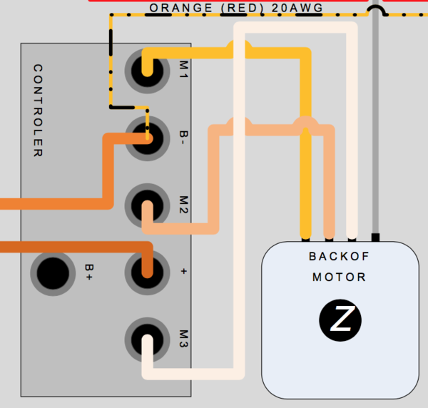 Motor-controller power connections |
| 8-pin Metri-Pack 150 (Mouser p/n 829-12047937) - Terminal: Mouser p/n 829-12084200 - Retainer: Mouser p/n 829-15324525 - Seal: Mouser p/n 829-15324973 - Seal: Mouser p/n 829-12059168-B 1. Motor Position (Cosine) / white 2. Motor Position (Sine) / blue 3. Motor Position (Ground) / black 4. unused 5. VDD (5V) / red 6. Shield / green 7. Temperature (negative) / yellow 8. Temperature (positive) / yellow |
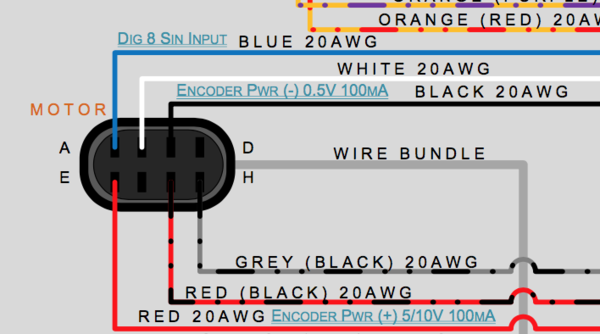 2013 motor sensor connectors |
Motor Alignment
FST Platform/Motor Alignment
Motor Commissioning
Motor commissioning refers to aligning the controller's sine wave programming against the motor using its position sensors.
Benefits
Maximum efficiency (avoids current applied wastefully)
Avoid any slippage.
Avoid misapplied torque which might wear on the bearings.
Motor Limits
The following regards what engineering constraints limit the power and RPM of the (IPM) Z-Force motor. Pre-IPM motors generated more heat for a given amount of power, so cooling was usually the first concern, but the IPM design pushes the frontier further so the topic is worth addressing.
RPM
The Z-Force motor is design-limited to 6,000 RPM as follows.
RPM is primarily limited by the inductance of the motor windings.
At low RPM, under full throttle, the current through the driven phase(s) of the motor ramps up from 0 to the maximum allowed by the controller pretty quickly, and you get full torque because you've got full current.
But the faster the motor turns, the faster the motor controller has to cycle the phases of the motor on and off, and eventually, you reach a point where there's not enough time (because of the inductance of the motor windings) for the current to ramp up to maximum before that phase has to be turned off and the next phase cycled on.
At that point, power starts to drop off, so very shortly after that, the motor won't have enough torque or power left to drive the load.
The mechanics of the motor could easily have been designed for higher RPM, but there's no point since you'll be current-limited anyhow.
Torque / Power
The easiest way to get more torque, and thereby more power (since power is proportional to torque times RPM), is to pump more current through the motor.
Several things can bottleneck that effort:
- First, the motor windings have a DC resistance because they're copper wires with fixed gauges and lengths.
- The bike's wiring external to the motor also has some DC resistance in it.
- If you apply more voltage to a fixed DC resistance, you'll get more current, but the batteries only give you ~110VDC to play with....and of course, the battery has a current limit of its own.
- You'll need to be sure the controller can handle the current as well; you won't go very fast once you smoke the controller.
- Since the motor rotates and therefore the windings have to be commutated (driven on and off in the proper sequence and speed), the motor's inductance also comes into play as discussed above about RPM.
- You could change some of this stuff fairly easily (higher-gauge wiring is pretty simple, though might be tough to fit in some of the tight confines the Zero's wiring is routed through), but other things are more difficult.
- To reduce the motor winding's DC resistance, you'd want to use heavier wire, but you wouldn't be able to get as many turns onto the same coil form.
- Fewer turns would create less inductance, which also helps allow higher current levels, but fewer turns also results in a weaker magnetic field for the same current, so you might actually reduce the torque the motor puts out.
- Then you'd also need to be sure you don't over-current the controller, or the batteries, and cooling everything involved becomes an additional topic.
It's kind of like asking what's the highest VO2 max an athlete can put out.
- It's not just about his lungs, it's about his heart, his muscles, his metabolism at a microscopic level, even about his mental attitude.
- Tweak any one thing and the system's whole balance shifts.
- That's why engineers make the medium-sized bucks!
Speed
Vehicle top speed can only be altered by the gearing (sprocket ratios).
Power output is not affected by gearing; only torque is.
So, a ratio yielding a higher top speed will result in lower torques throughout the range, resulting in slower accelerations from start.
References
What is the limit of a Zero motor?
Controller
FST Platform/Motor Controller
Controller Operation
FST Platform/Motor Controller/Operation
Controller Alignment
FST Platform/Motor Controller/Alignment
Controller Versions
FST Platform/Motor Controller/Versions
Controller Mounting
FST Platform/Controller Mounting
Controller Uncovering
FST Platform/Controller Uncovering
Controller Heatsink
FST Platform/Motor Controller/Heatsink
Controller Connections
FST Platform/Motor Controller/Connections
Controller Feature Usage
FST Platform/Motor Controller/Feature Usage
Controller CAN Diagnostics
FST Platform/Motor Controller/CAN Diagnostics
Controller Configuration
FST Platform/Motor Controller/Configuration
Controller Cover
FST Platform/Motor Controller/Cover
Controller Cover Removal
FST Platform/Controller Uncovering
Source: zeromanual.com/wiki/FST_Platform/Unofficial_Service_Manual · Wayback capture of 2025-05-17 · wiki last edited 2 May 2020 00:04. Community-written content from the Unofficial Zero Manual, reproduced for preservation; not written or verified by OpenZero. Links to pages that were not mirrored go to the Wayback Machine.