Powertrain
The powertrain includes all of Zero's power storage and delivery components including the battery, but this section focuses on the motor, power delivery via the controller, and their inputs via throttle and drive mode configurations.
Licensing
- For a time, Zero openly offered powertrain components in a licensed manner for prototyping and other uses.
- Currently, probably for reasons of liability and support overhead, this is not publicly offered but does seem available on request for companies wanting to develop products where Zero's powertrain is a good fit.
- See Zero's Z-Force Powertrain Solutions page which has a contact form.
Throttle
The Zero throttle is a very straightforward twist-grip motorcycle control that operates a sensor instead of pulling on a mechanical cable or operating hydraulics.
Zero switched the throttle supplier from a Magura with a linear potentiometer to a Bitron with a Hall-effect sensor in 2015 which changed how the wiring works.
Connections
The Zero throttle connects directly to the controller, so anything you do related to the throttle signal can compromise the operation of the bike if there's an electrical fault or discrepancy.
Example: [Sudden braking followed by no motor/throttle response on highway2016 FXS]
Customization
See Drive Modes to customize throttle input interpretation as an owner.
Use the mode control for "Custom" mode on 2014+ or "Eco" on earlier models to set the maximum torque the throttle applies.
This also directly changes how quickly torque ramps up for a given throttle twist/position.
Advanced Customization
The Sevcon motor controller settings are where most of the throttle interpretation happens.
Replacement
TODO...
Assembly
The return spring cannot be tensioned while disassembled throttle is on the handlebar. Throttle must be removed to place the spring end correctly. see video from Harlan Flagg: https://www.facebook.com/harlanflagg/videos/1364143910276196/
Troubleshooting
One report of a "snatchy" throttle turned out to have this explanation:
There is a black adjusting screw which holds the pinion gear of the throttle in place or for adjustment.
The pinion gear had moved to the right and caused the spring clip for throttle return to pop out of the slot.
This was clicking through the gears and causing a notchy throttle feel.
Resolution: Reset the pinion location and tighten the screw.
Magura Throttle
The 2012-2014 stock throttle is a 5kOhm Magura throttle
Basic details
The Magura Twist Throttle has a 0-5kΩ output.
Comes with matching grip for opposite side.
7/8" (22mm) handle bar fit
68" long control cable
Weight: 0.5 lbs
Connectors
Three wire output directly to the controller.
| Wire | Function | Destination | Illustration |
|---|---|---|---|
| Blue | Throttle High | Sevcon Pin 34 | 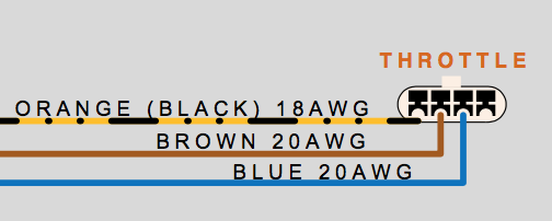 |
| Brown | Wiper | Sevcon Pin 22 (analog) | 〃 |
| Orange/Black | Throttle Low | B- Sevcon terminal | 〃 |
Bitron Throttle
2015+ models use a new HAL-based (Hall-effect active device) sensor from Bitron which can't be replaced easily by Domino or similar
Product reference: Bitron HAL-based throttle
Connectors
8 wire output, bundled into two pairs of 3 wires for potentiometer outputs.
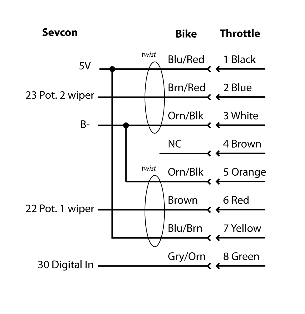
The hall-effect sensor may be a potentiometer wired up as a voltage divider as follows:
| Wire | Twist | Voltage |
|---|---|---|
| Brown | None | 0.5 |
| 〃 | Full | 4.5 |
| Brown/Red | None | 4.5 |
| 〃 | Full | 0.5 |
Regen
Regen refers to Regenerative Braking
Operation
The Sevcon Controller can enter a regeneration mode where it captures momentum from the motor and charges the battery.
The battery must accept incoming power for this feature to work, and the controller must manage the process.
Operating Range
Regen for Zeros operates between 12mph (where the motor cannot produce enough voltage to naturally power through the controller) and 4500 RPM (70mph in default gearing).
This band can be adjusted in MBB settings.
Level
Regen levels are defined/set in terms of percentage of maximum allowable levels, so 0-100%.
That 100% maps to a 40A recharge limit setting in the Sevcon controller, equivalent to 10% of the maximum discharge rate of a Gen4 size 4 controller.
The 100% setting also corresponds to 60% of the 72Nm torque limit also specified.
The recharge limit may be set up to 91A via Sevcon setting or higher by a dummy value (65535?).
Zero sets regen levels to preclude rear wheel lockup, so raising the limit is a risk that ABS cannot directly control.
Regen has the same effect for SR/DSR models as for S/DS.
Efficiency
The recharge efficiency of regen is typically that 10% of the energy used to climb an incline can be returned on the corresponding descent.
Triggers
- Normal regen is triggered by relaxing the throttle.
There is a position just above the resting position where an actual neutral torque is achievable.
The MBB has a setting in mV for the potentiometer output of the throttle to trigger regen.
Adjusting this is not normally effective unless changing throttle types. - Brake regen is triggered by the same signal that turns on the brake light:
A contact switch against the front brake lever will engage the brake light (and regen); the hydraulic piston and the switch engage simultaneously by default.
Rear brakes engage pad contact and the brake light (and regen) simultaneously, but require some amount of travel before they engage.
Drive Modes
The Zero platform has always offered a simple control for switching throttle and regen mappings through MBB-Sevcon interaction.
Gen1 (2009-2013)
- Through 2013, only Eco and Sport modes were available, where Eco was the customizable mode but had the Eco default as listed below.
- The modes are selected with a rocker switch on the left part of the steering head bracket forward from the handlebars.
Gen2 (2014-)
- 2014 models introduced a separate Custom mode and made Eco mode fixed.
- Modes are selected by pressing a selector button on the right hand switch assembly; the selected mode then activates when the throttle is released for a couple of seconds.
- The SRF Model introduced "Street, Sport, Eco, Rain and up to 10 programmable custom modes".
- Custom traction control modes were also introduced.
| Mode | Max Speed | Max Torque | Max Regen | Max Regen Brake |
|---|---|---|---|---|
| Eco | 70 mph | 40% | 66% | 100% |
| Custom | 70 mph | 100% | 40% | 66% |
| Sport | 98 mph | 100% | 40%? | 66%? |
Gen2 Customization
Many riders make their own Custom mode settings. There are many options that all involve tradeoffs.
- 0% (-20%) Max Regen
This enables a "coasting" mode which is very efficient, in allowing the rider to let the bike's momentum carry it forward for a while.
This also helps transition the bike from accelerating to decelerating, since the regen levels come on in a step-wise fashion, which minimizes the dive on the suspension by providing an intermediate step.
NOTE: This has one disadvantage at 0%: in extremely low traction scenarios, this can lead to dangerous fishtailing where the rear wheel starts to slip, in that it can be very difficult to slow it down. - 100% Max Brake Regen
Most riders seem to leave this setting at 100% in order to get the most out of their rear brake. - Lower Top Speed (60 or 70mph, say)
This creates a "poor man's" cruise control, where the throttle has no effect at the top end, only ensuring that a specific speed is met.
This can be useful when trying to get a maximum or ensured amount of range. - Lower Max Torque (30% or less)
This can be useful in wet or reduced traction conditions.
Torque setting is mostly about the torque ramp rate (how much torque achieved with a given amount of throttle twist).
By reducing the ramp rate, the onset of a loss of traction is much easier to control and recover from.
Most riders just switch to Eco mode in the rain, but using Custom mode for this can also be effective.
Motor
All of Zero's motors are air-cooled and mounted on a shaft that is aligned with the front pivot of the swingarm so that transmission tension is perfectly aligned with swingarm movement.
| Gen | Brand | Designation | Years | Models |
|---|---|---|---|---|
| Gen1 | Agni/Saietta | 95-R alt | 2009-2011 | S/DS/X/MX |
| 〃 | Motenergy | ME0810 | 2011-2012 | X/MX |
| 〃 | 〃 | ME0913 | 2012 | S/DS |
| Gen2 | Z-Force Motor | 75-5 | 2013 | FX/MX/XU |
| 〃 | 〃 | 〃 | 2014-2015 | FX |
| 〃 | 〃 | 〃 | 2016 | FX/FXS |
| 〃 | 〃 | 75-7 | 2013-2016 | S/DS/MMX |
| 〃 | 〃 | 75-7R | 2014-2015 | SR |
| 〃 | 〃 | 75-7R (IPM) | 2016-present | SR/DSR |
| 〃 | 〃 | 75-5 (IPM) | 2017-present | FX/FXS/S/DS (Longbrick) |
| Gen3 | 〃 | 75-10 (IPM) | 2020-present | SRF/SRS |
Agni Motor
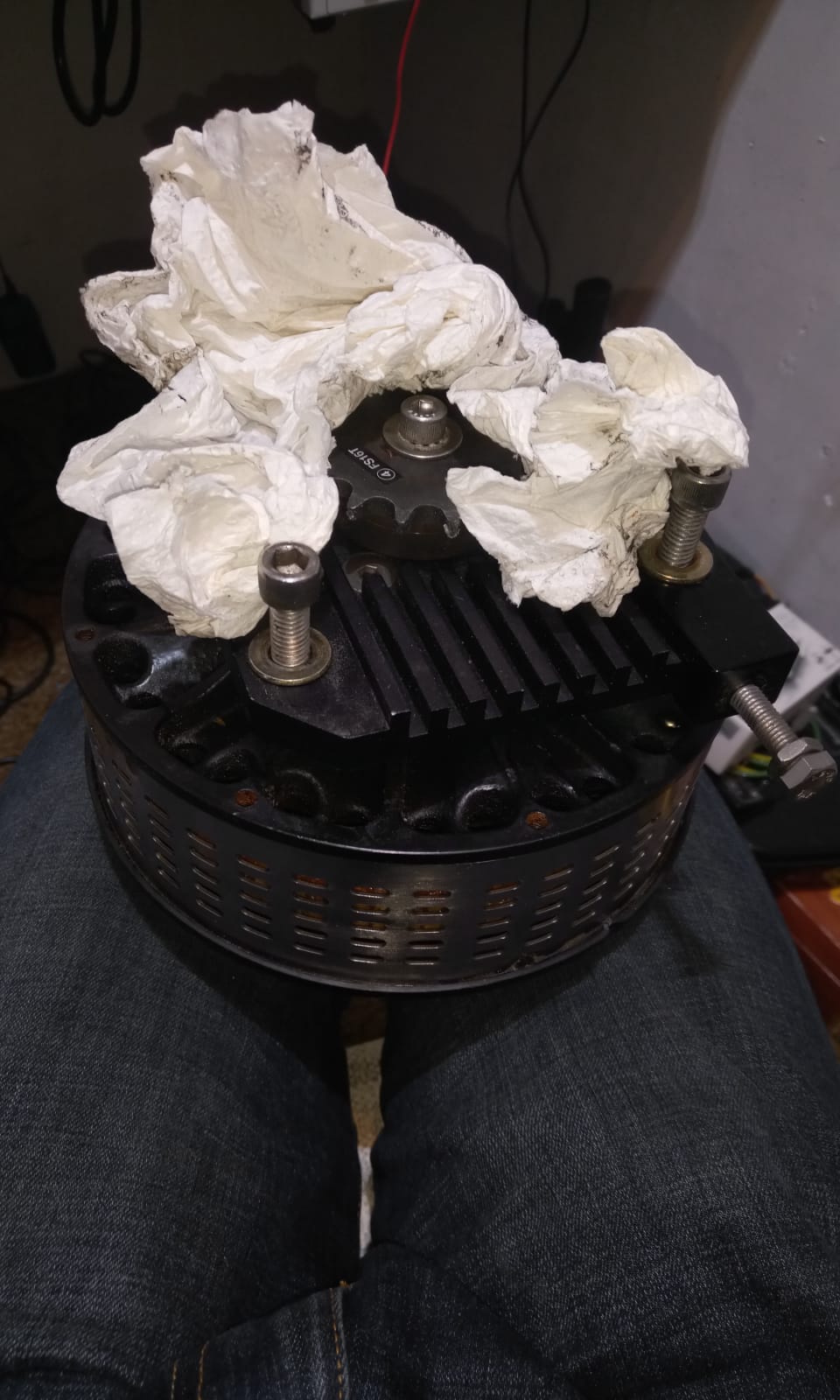
From 2009 to 2012, Zero used brushed DC Agni/Saietta 95-R motors.
These have known quality issues after time and Zero offers many owners a Z-Force motor upgrade or complete trade-in for remaining 2014 models.
Basic Facts
Shaft ⌀19mm
6mm keyway
~22 kW (30 HP)
Chain Specs
420 chain specs: .500" pitch / .3125" roller diameter / .250" roller width / .227" sprocket width.
41 sprocket teeth will engage 420 chain links, but they're made for .306" dia. rollers and a #41 sprocket / 420 chain combo will wear quickly.
Some sprocket places sell '41/420' sprockets, but there's no such thing.
References
2012 to 2013 motor upgrade info
Z-Force Motor
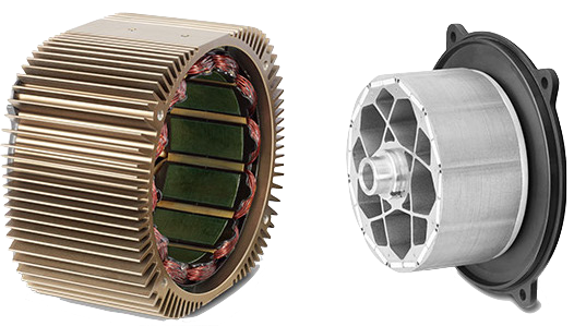

For the 2013+ models (Gen2 and Gen3), Zero has their own motor design, trademarked "Z-Force".
Features
- Sealed
- Air-cooled (via finned casing)
- Brushless
- Permanent-magnet rotor
Operation
It is a 3-phase brushless DC (BLDC) electric motor which is roughly described as a permanent magnet AC synchronous (PMAC) motor since the controller is continuously adjusting the phase angle of the field to the rotor's current position and speed.
The field must apply synchronously to the rotor, so the calibration between the position sensor and the controller is critical for efficiency, minimizing wear on the bearings, and minimizing heating of the windings and magnets.
Motenergy's Clone
Motenergy makes an unlicensed generic derivative, the ME1507, of the same form factor, rated for much lower outputs and seems to differ from Zero's motor in key ways.
From Motenergy's ME1507 product page, it's clear that they're advertising a model on par with the 2016 IPM update:
The ME1507 is an Radial Air Gap, Permanent Magnet Synchronous Motor (PMSM) with an Internal Permanent Magnet Rotor (IPM). Designed for battery pack voltages of 100 VDC or less. Maximum rotor speed of 6000 rpm. Continuous current of 200 amps, and continuous power of 17 kw. Weight of 44 pounds.
Motor theory
IPM vs SPM for a different motor control regime but some principles translate to the Z-Force motor.
Efficiency
Range vs Speed by Patrick Truchon discusses the theory and measurements in depth.
Does Gear Size Affect Range? by Patrick Truchon with more theory!
Z-Force Motor 75-5
The XMX Platform uses the 75-5 variant of the Z-Force Motor, as well as the Longbrick S/DS models (2017-present).
The -5 suffix indicates a 5cm extruded width.
Z-Force Motor IPM Update
In 2016, Zero introduced an interior permanent magnet (IPM) design as distinguished from a surface permanent magnet (SPM) design of the original motor introduced in 2013.
- An IPM design places the rotor magnets in physical slots within its circumference, instead of binding the magnets to the rotor's circumference via special epoxies.
- The IPM design reduces the heating associated with developing magnetic flux and distributes the heat produced more evenly.
This allows the motor to operate at higher outputs while producing less heat overall and concentrating heat production where it dissipates more easily.
In practice, this avoids hitting thermal limits which require cutbacks to protect the motor windings.
Controller Programming Note
- The IPM design motor apparently involves custom Zero programming of the Sevcon controller for the encoder, so off the shelf DVT software cannot perform alignment/commissioning but can apply settings / DCF files and restore them.
Production / Rollout
- 2016 models S/DS/SR/DSR/FXS have the IPM design.
- FX and S/DS models with a 3-brick battery retained the SPM design (presumably to be phased out with inventory).
- As of 2017, statements from Zero indicate that once the IPM motor design was in production, SPM motor production ceased, and all replacements of SPM motors would use IPM motors.
References
Zero livestream announcing 2016 upgrades
Zero livestream presentation with Ryan Biffard about the Z-Force motor IPM upgrade
Z-Force Motor Mount/Torque Update
In 2017, the Sevcon controllers were updated ("4.5" is the unofficial revision) to support more current to the motor.
The Drive Belt was also reinforced and widened to apply more torque through the transmission and be more robust against interference.
Accordingly, the motor shaft is now splined instead of keyed so the motors and sprockets are not compatible across the 2016-2017 year-line.
Motor Mounting
On the motor there are 8 M8 bolts holding the motor in place: 4 on the drive side, 4 on the rear side.
Those bolts only have about 12Nm of torque on them.
References
Burton's 2013 to 2014 motor swap thread shows the most detail about the physical mounting of the motor.
Motor Removal
Tools
- M8 Allen socket
- Torque wrench
Steps
First you have to remove the swing-arm (that is pretty straight forward) some big bolts in the pivot and disconnet the shock.
You can leave the brake lines attached and just move the swingarm out of the way when the motor needs to come out. 3. Unplug the sensor connector near the front of the contoller on the riders right side of the bike. 4. Un-bolt the 3 phase leads to the motor controller.
It's a good idea to insulate them just in case the bike is powered on. 5. Disconnect the motor from the bike.
On the motor there are 8 M8 bolts holding the motor in place: 4 on the drive side, 4 on the rear side.
Those bolts only have about 12Nm of torque on them. 6. Once you have the motor disconnected and un-bolted from the frame, it should slide out towards the back.
Motor Bearing Replacement
This replaces the motor bearings on Gen2 Z-Force motors.
Tools
- C-clip pliers
- M10 tensioner
- Loctite 648
- Hub puller (to extract the bearings)
- Replacement bearings (front and rear are both 6006-2RS on an FX used below)
Notes
- In these instructions, the front of the motor is the left/shaft-side, and the rear of the motor is the right/encoder-side.
Steps
- Prepare a clean workspace, removing all debris and metal tools that you are not directly using.
 Warning: |
The rotor magnets are so strong they rip tools out of your hand and they attract every single metal filing that might be near by. |
| 2. Remove the motor from the bike. | |
| 3. Removed the belt pulley: | |
| 1. Remove the M10 countersunk bolt. | |
| 2. Put two thin pieces of metal under the pulley, and drive two M6x1? bolts into the two threaded holes of the pulley to lift the pulley off. | |
| 4. Gently pry the front cover off. |
It will most likely be stuck on the rotor so you'll be lifting the rotor out of the housing with it.
It is actually quite straighforward to pull apart, but requires a lot of force.
You can built a little chair (width of the plate, you put it on the cooling wings) with an M10 tensioner.
Then you bolt an M10 eye-bolt (or T-handle) on the pulley so you can pull on the shaft really hard (about 200lbs), and the rotor will pull out on the shaft along with the drive plate and bearings.
| Warning: |
Once you have the shaft and rotor out, be careful as it is highly magnetic and you can get your fingers pinched quite easily on it. |
At that point, the rotor should be loose on the shaft. 5. If you have to remove the rear bearing, remove the c-clip holding the rotor laminations on the shaft, use a marker or something to mark the front and back of the rotor and how it is aligned on the shaft because you are going to take it off.
The end of the rotor on the back side is aluminum so do not press on it.
It houses tiny magnets that the motor position sensor (encoder) reads; damage to this will ruin the rotor.
| Warning: |
It is important that it goes on in the exact same direction, otherwise the motor could spin backwards. |
| 6. Once you have the rotor and the shaft labeled so you can get them back together exactly the same way, slide the rotor laminations off the shaft. | |
| 7. Clean the shaft and the inside of the laminations. | |
| 8. Apply a lot of loctite 648 on the shaft and lamniations, then slide them back together. |
Ensure that they go together the same way that they were before.
Endure that the loctite 648 gets well-distributed between the shaft and the laminations to make a solid bond. 9. Press the rotor out of the front cap
The bearing is held into the cap by a retainer so the rotor is pressed from the bearing. 10. Remove the front bearing retainer and press the bearing out of the cap. 11. Put the c-clip back on, put the bearing back on (or put a new bearing on since removing a bearing without damaging it is quite hard, the front and rear bearings are both 6006-2RS).
| | |
| --- | --- |
| { loading=lazy } **Warning:** | When you put the new bearing on, make sure you just push on the inner race for the press fit, if you push on the outer race it will transfer the force through the balls and likely damage them. |
The bearing should be a press fit; if it slips on or off easily, you should glue it on with the loctite 648.
- Let the 648 cure for a few hours before putting the motor back together.
-
To put the motor back together, just do the same thing you did to pull it apart, but opposite.
Ensure that the wave-spring is still in the bottom of the bearing pocket at the bottom of the motor.
Warning:Be careful to not let the rotor slam back into place, that could damage the bearing Temporarily lining the inside of the stator with a plastic sheet can prevent damage to the stator and rotor.
Make sure you control the rotor: use the little chair and unscrew the tensioner to let the magnetic forces pull it back in slowly.
Once it is almost all the way in, the bearing will catch on the bearing pocket.
At that point, it might take a little jiggling around and some force on the end of the shaft to get it to pop into place, then it could take a bit more force to get the drive-plate to re-engage with the stator case.
Motor Shaft
Pre-2017
The motor shaft is keyed; the key has a square cross section.
Measurements
- Dimensions seem to be ¼” square ⨉ 2.0” length (expressed in metric on drawings).
- Ends 5mm from shaft end.
- Shaft diameter is ⌀28.275mm+0-0.021
- Shaft length extends 66.675mm beyond the motor face minus 4mm for raised parts of the face.
2013 models had a minor recall about the shaft key coming loose, but this was a design revision that has not recurred.
2017+
The motor shaft is splined to allow higher torque transmission.
Rumor has it (via Harlan at Hollywood Electrics) that the spline is supposed to match a Kawasaki KX250F as well as a Yamaha YZ450F.
Motor Sounds
Motor Whirring
The motor on 2013+ models makes a white noise sound at very slow speeds when rotated (by the wheels or shaft).
This is also described as a "whirring sound".
This is alluded to by the term "cogging".
This is normal as long as it sounds like white noise and occurs as described below.
Video Guide
- Strange noise Zero DS 2017 provides a reference for comparison:
Related Confirming Symptoms
- The noise should only occur while the motor is rotated by external input (pushing the bike around or rotating the shaft).
- The noise should not while under power (when the motor is driving its own rotation).
- The bike should gently resist being pushed while the noise is audible.
Causes
- The direct cause is the controller applying a white noise field to the motor at very slow speeds.
- At least one connected battery's contactor must have been engaged for this to occur.
This can occur while keyed on, or while charging.
Effects
- There are no detrimental effects, when the sound occurs by design.
- The purpose is for the controller to detect and maintain precise knowledge of the motor's rotor angle.
- This ensures that, if the throttle demands operation, the controller will apply the field correctly to the rotor.
- You may infer that at least one contactor is engaged to power the controller.
- If the bike is keyed on, you may infer that the motorcycle should be ready to drive.
(aside from the kickstand and kill switch safety interlocks).
Motor Whine
While moving, the motor tends to make a solid smooth tone resonant with the motor's rotational speed.
Related Confirming Symptoms
- Typically, this occurs while the motorcycle is traveling at speeds above 10mph.
- Most noticeable between 15-30mph (30-50kph).
Causes
- The motor shaft bearings are likely the primary generator of this resonant noise.
Effects
- None; this is normal and expected.
Motor Wiring
The Z-Force motor's stator is connected to the controller for power and position feedback.
| 3-phase / Y-shaped (120° phase offset) power inputs from the controller. 1. A (M1) 2. B (M2) 3. C (M3) |
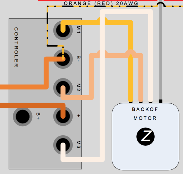 Motor-controller power connections |
| 8-pin Metri-Pack 150 (Mouser p/n 829-12047937) - Terminal: Mouser p/n 829-12084200 - Retainer: Mouser p/n 829-15324525 - Seal: Mouser p/n 829-15324973 - Seal: Mouser p/n 829-12059168-B 1. Motor Position (Cosine) / white 2. Motor Position (Sine) / blue 3. Motor Position (Ground) / black 4. unused 5. VDD (5V) / red 6. Shield / green 7. Temperature (negative) / yellow 8. Temperature (positive) / yellow |
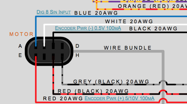 2013 motor sensor connectors |
Motor Alignment
Motor alignment refers to physical alignment of the motor with the frame and swingarm so that power is transmitted correctly to the final drive.
The back side of the motor (encoder side) has screw jack bolts that let you tweak the motor position.
Mostly this is only needed when (re)installing the motor.
Steps
- Loosen the four M6 socket head screws.
- Adjust the portion of the silver nut that is not wedged into the slot on the motor.
Motor Commissioning
Motor commissioning refers to aligning the controller's sine wave programming against the motor using its position sensors.
Benefits
Maximum efficiency (avoids current applied wastefully)
Avoid any slippage.
Avoid misapplied torque which might wear on the bearings.
Motor Limits
The following regards what engineering constraints limit the power and RPM of the (IPM) Z-Force motor. Pre-IPM motors generated more heat for a given amount of power, so cooling was usually the first concern, but the IPM design pushes the frontier further so the topic is worth addressing.
RPM
The Z-Force motor is design-limited to 6,000 RPM as follows.
RPM is primarily limited by the inductance of the motor windings.
At low RPM, under full throttle, the current through the driven phase(s) of the motor ramps up from 0 to the maximum allowed by the controller pretty quickly, and you get full torque because you've got full current.
But the faster the motor turns, the faster the motor controller has to cycle the phases of the motor on and off, and eventually, you reach a point where there's not enough time (because of the inductance of the motor windings) for the current to ramp up to maximum before that phase has to be turned off and the next phase cycled on.
At that point, power starts to drop off, so very shortly after that, the motor won't have enough torque or power left to drive the load.
The mechanics of the motor could easily have been designed for higher RPM, but there's no point since you'll be current-limited anyhow.
Torque / Power
The easiest way to get more torque, and thereby more power (since power is proportional to torque times RPM), is to pump more current through the motor.
Several things can bottleneck that effort:
- First, the motor windings have a DC resistance because they're copper wires with fixed gauges and lengths.
- The bike's wiring external to the motor also has some DC resistance in it.
- If you apply more voltage to a fixed DC resistance, you'll get more current, but the batteries only give you ~110VDC to play with....and of course, the battery has a current limit of its own.
- You'll need to be sure the controller can handle the current as well; you won't go very fast once you smoke the controller.
- Since the motor rotates and therefore the windings have to be commutated (driven on and off in the proper sequence and speed), the motor's inductance also comes into play as discussed above about RPM.
- You could change some of this stuff fairly easily (higher-gauge wiring is pretty simple, though might be tough to fit in some of the tight confines the Zero's wiring is routed through), but other things are more difficult.
- To reduce the motor winding's DC resistance, you'd want to use heavier wire, but you wouldn't be able to get as many turns onto the same coil form.
- Fewer turns would create less inductance, which also helps allow higher current levels, but fewer turns also results in a weaker magnetic field for the same current, so you might actually reduce the torque the motor puts out.
- Then you'd also need to be sure you don't over-current the controller, or the batteries, and cooling everything involved becomes an additional topic.
It's kind of like asking what's the highest VO2 max an athlete can put out.
- It's not just about his lungs, it's about his heart, his muscles, his metabolism at a microscopic level, even about his mental attitude.
- Tweak any one thing and the system's whole balance shifts.
- That's why engineers make the medium-sized bucks!
Speed
Vehicle top speed can only be altered by the gearing (sprocket ratios).
Power output is not affected by gearing; only torque is.
So, a ratio yielding a higher top speed will result in lower torques throughout the range, resulting in slower accelerations from start.
References
What is the limit of a Zero motor?
Controller
The motor controller takes power from DC battery bus, encoding three-phase sine waves to match the motor's position sensor to apply torque precisely to the motor.
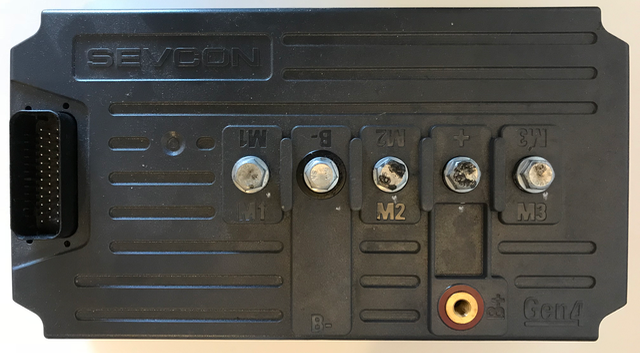 Sevcon Gen4 Size 6 Controller Top
Gen2 motor controllers are all Sevcon Gen4 motor controllers, mostly Size 4 (S/DS) and Size 6 (SR/DSR), with Size 2 for the older XU model.
The sine waves are constructed by power transistors operating in a pulse-width modulation (PWM) capacity.
The power is applied to the motor in synchronization with the current speed and position of the rotor.
Controller alignment (motor commissioning) is the process of tuning all of this for maximum efficiency and to avoid any slippage.
Controller Operation
The controller is a switching MOSFET power supply that creates 3 phased sine wave outputs to drive the motor via Pulse-width modulation (PWM).
The switching attempts to produce a smooth sine wave to each output terminal via Space vector modulation strategy of PWM.
The motor has 3 stator (casing-embedded) windings at 120° equally spaced offsets around the circumference.
- Each winding pulls from one motor terminal's output from the controller.
- Each winding electromagnetically pulls on the rotor.
- The forces need to balance out, not leading to a net lateral force on the rotor and shaft.
- It also shouldn’t precess or wobble or slip.
The process of making the sine waves is “encoding”.
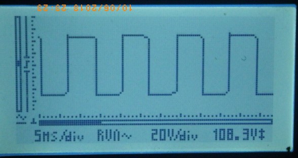 MY2017 Zero SR. Scope at Sevcon M3 Output Terminal
Controller Alignment
Alignment is the calibration of the controller sine wave production to match the controller output to the motor's position precisely.
- This is performed once/first by Zero's Motor Commissioning process and then repeated later as a recalibration.
- It should generally be performed periodically as a preventative maintenance step.
The motor has sensors for encoder alignment to tell the exact angle of rotation of the rotor.
- If those sensors are inaccurate, encoding can be rough or fail entirely.
- The sensors are embedded within the motor so for owners they just compensate in the controller for the drift, or swap the motor if the signal is bad enough that the controller can’t work with it.
Controller Versions
| Bike | Controller | Limits | |||
|---|---|---|---|---|---|
| Years | Models | Manufacturer | Model | Input Voltage | Phase Current |
| 2009-2011 | S/DS | Alltrax | AXE4855 refs: [8] [9] | 48V | 500A |
| 2012 | XU | Sevcon | Gen4 Size 2 | 120V | 220A |
| 〃 | S/DS | 〃 | Gen4 Size 4 | 〃 | 420A |
| 〃 | X/MX | Alltrax | AXE7245 refs: [10] [11] | 72V | 450A |
| 2013-2016 | XU | Sevcon | Gen4 Size 2 | 120V | 220A |
| 〃 | S/DS/FX/FXS/MMX | 〃 | Gen4 Size 4 | 〃 | 420A |
| 〃 | SR/DSR | 〃 | Gen4 Size 6 | 〃 | 660A |
| 2017+ | S/DS/FX/FXS/MMX | 〃 | Gen4.5 Size 4 | 〃 | 550A |
| 〃 | SR/DSR | 〃 | Gen4.5 Size 6 | 〃 | 775A |
2017 “Gen4.5”
2017 models reference higher current ratings without publicized evidence of a Sevcon model change.
These improvements seem to be in choosing MOSFETs with increased power switching efficiencies to allow higher continuous and peak current levels.
“Gen4.5” has been a term heard describing these improvements.
Gen4 Size 6 Controller
Sevcon Gen4 Size 6 Controller Top
- 
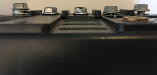
Sevcon Gen4 Size 6 Controller Top Terminals
- 
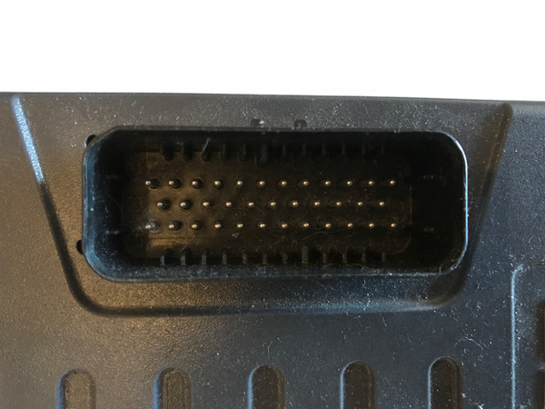
Sevcon Gen4 Size 6 Controller Terminals Left Side
- 
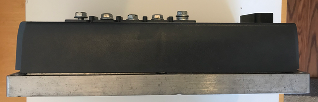
Sevcon Gen4 Size 6 Controller Connector
- 
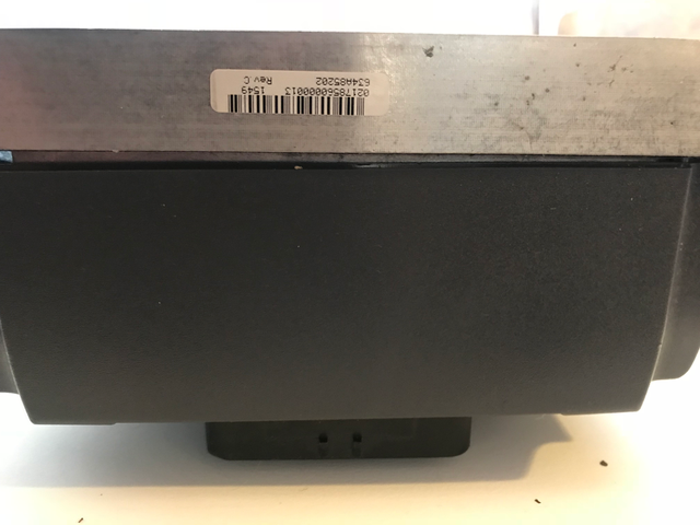
Sevcon Gen4 Size 6 Controller Left Side
- 
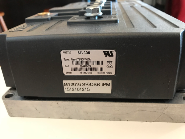
Sevcon Gen4 Size 6 Controller Front
- 
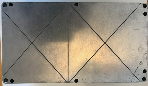
Sevcon Gen4 Size 6 Controller Rear
- 
Sevcon Gen4 Size 6 Controller Bottom
Gen4 Size 6 Controller Internals

Sevcon Gen4 Size 6 Controller Connection Front
- 
Sevcon Gen4 Size 6 Controller Connections Profile
- 
Sevcon Gen4 Size 6 Controller Connectors Left Side
- 
Sevcon Gen4 Size 6 Controller Casing
- 
Sevcon Gen4 Size 6 Controller Top
Controller Mounting
Controller Location
The controller is positioned in the lowest part of the forward face of the frame, just in front of the motor.
Controller Fasteners
A heatsink is fastened to its surface for radiative cooling, with a thermal paste between to maximize heat transfer via contact/conduction.
4 M6 bolts secure the controller baseplate to the frame.
- For size 2 and size 4 controllers, the base plate is 12mm thick.
Controller Uncovering
This gains access to the motor controller on XMX Platform models.
| Warning: |
This exposes high-voltage terminals that can damage tools, equipment, or cause injury or death if not de-energized. Ensure the bike is fully de-energized or that you are using professional methods and safety precautions. |
Tools
- 3mm Allen key
Steps
- Key the bike off and unplug any chargers attached to the bike.
- Remove the 5 bolts securing the side cover ahead of the motor with the 3mm Allen key.
- Remove the side cover.
Controller Heatsink
The underside face of the controller is directly covered by a finned heatsink that faces downwards toward the rear wheel and swingarm.
- The heatsink varies in size with the size of the controller.
- A thermal paste is applied between the heatsink and baseplate to maximize heat transfer via contact/conduction.
- The rear shock connects just ahead of the heatsink to the frame center tube.
Controller Connections
| Main terminals are, in order from front to rear: M1, B-, M2, B+, M3. For Size 4 and Size 6, the bolts are all M8 with a torque setting of 11Nm±2Nm; bolts should engage a minimum of 10mm and thread depth is 15mm. For Size 2 (2013XU), the bolts are all M6 with a torque settings of 7Nm±2Nm. - M-terminals supply the motor with its rotating field in three phases. Each gets a sine wave that is offset by 0, 120, 240 degrees. - B+ and B- connect to the battery power at positive and negative, respectively. |
Motor-controller power connections |
| Connector info (see AMPSEAL Automotive Plug Connector and Header Assembly (PDF, English)) More connector info (look at bottom for pins) |
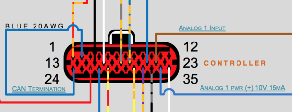 2013 Gen4 Size 4 Controller signal connector |
Diagnostic Cables
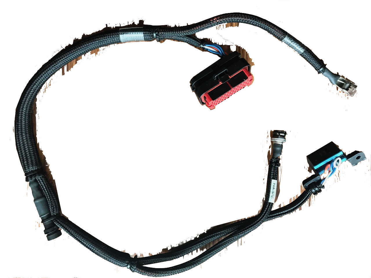
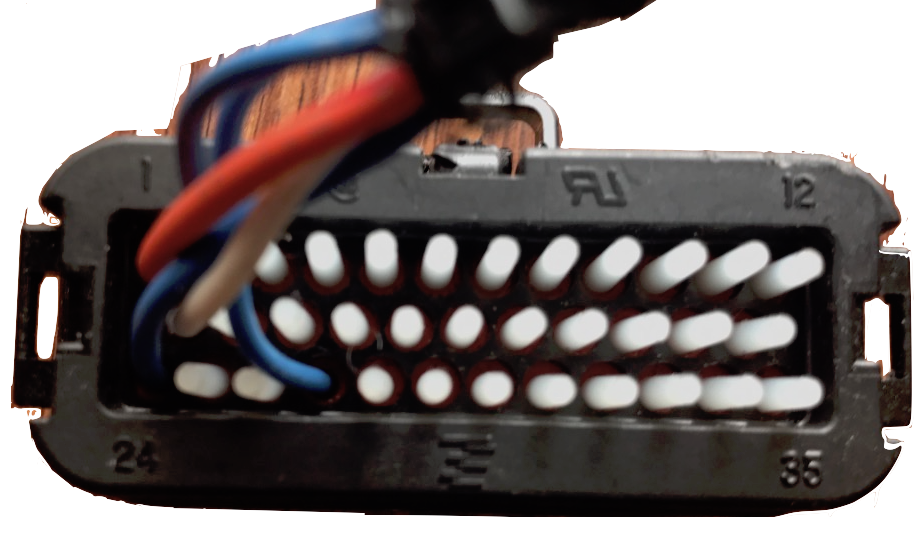
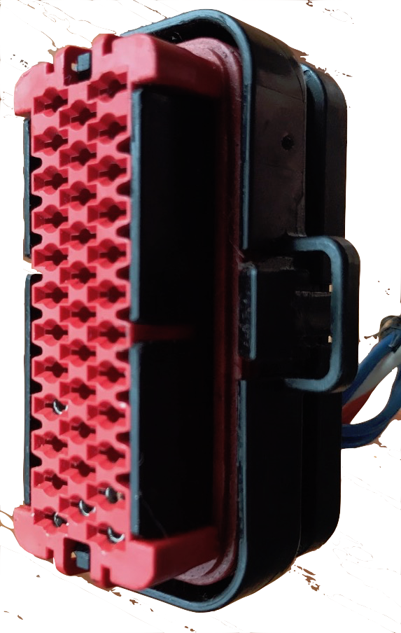
Zero Sevcon programming cables are part #86-06747 connected as follows:
- Pin 1 is "Key Switch In": power for the logic circuits.
- Pin 2 is linked to pin 24 via 120Ω resistor to tell the Sevcon that it's at the CANBus termination.
- Pin 13 is "CAN High".
- Pin 27 is "CAN Low" in the Sevcon manual (pin 24 also is, unless used for termination signal).
Controller Feature Usage
This describes how the Sevcon controller's features are used on Zero models.
Throttle
Sevcon provides the throttle with two mappings:
- Mapping voltage to value in the first place (separately for forward and reverse)
- An "input characteristic" profile which has linear, curved, crawl, and user-defined segmented options.
The controller also supports:
- Control modes targeting speed (used through 2012) versus torque (used in 2013+).
The control mode translates the throttle signal into motor operation, so it makes the throttle target a speed or a level of torque. - Dual throttle inputs. - Regen proportional to the throttle. - Directional throttle. - Speed limit proportional to throttle. - Reverse speed limit.
Regen
The Sevcon controller manual refers to regen as braking, and has a number of recommendations and features disabled to help prevent wheel lockup for "on-highway applications".
Braking
The Sevcon can also apply reverse torque as braking or a reverse gear, and supports separate speed and torque limits while the motor is rotating in reverse, very important if used on a Zero since motorcycles are unstable when reversed so must operate within human walking speeds.
OEM Programming
Zero programs the Sevcon controller for their needs, above and beyond DOT, NHTSA, and EU vehicle manufacturing standards.
Some of this is a bunch of settings and some of this seems to be a custom version of the firmware code.
The new IPM motor may have demanded further customization than previous models, where custom firmware code is particularly relevant.
Settings can be changed and restored, but not code without some OEM-supported technical assistance.
Controller CAN Diagnostics
Via the MBB logs or the console, emergency (EMCY) entries related to SEVCON will be CAN controller events from the Sevcon Gen4 drives.
Example logged events
via Re: Sudden braking followed by no motor/throttle response on highway(2016 FXS)
07004     06/03/2017 09:30:18   SEVCON CAN EMCY Frame      Error Code: 0x5000, Error Reg: 0x40 Sevcon Error Code: 0x46c3, Data: 0x04 0x01 0x00 , Unknown
07005     06/03/2017 09:30:18   SEVCON CAN EMCY Frame      Error Code: 0x   0, Error Reg: 0x00 Sevcon Error Code: 0x46c3, Data: 0x00 0x00 0x99 , Unknown
07006     06/03/2017 09:30:18   SEVCON CAN EMCY Frame      Error Code: 0x5000, Error Reg: 0x40 Sevcon Error Code: 0x46c3, Data: 0x04 0x02 0x00 , Unknown
07007     06/03/2017 09:30:18   SEVCON CAN EMCY Frame      Error Code: 0x   0, Error Reg: 0x00 Sevcon Error Code: 0x46c3, Data: 0x00 0x00 0x99 , Unknown
07008     06/03/2017 09:30:18   SEVCON CAN EMCY Frame      Error Code: 0x5000, Error Reg: 0x40 Sevcon Error Code: 0x52c3, Data: 0x00 0x00 0x00 , Unknown
07009     06/03/2017 09:30:18   SEVCON CAN EMCY Frame      Error Code: 0x5000, Error Reg: 0x40 Sevcon Error Code: 0x46c3, Data: 0x0c 0x10 0x00 , Unknown
07010     06/03/2017 09:30:18   Restarting Sevcon to clear cutout fault
07011     06/03/2017 09:30:18   Module 00                  vmod: 112.127V, batt curr: 65498A
07012     06/03/2017 09:30:18   Module 01                  vmod: 112.156V, batt curr: 65506A
07013     06/03/2017 09:30:19   Sevcon Turned Off
CAN message examples
ID    b0 b1 b2 b3 b4 b5 b6 b7
"81";"00 31 04 C3 4D 00 00 00"
"81";"00 31 14 C3 4D 00 00 00"
"81";"00 82 10 0F 53 02 00 00"
"82";"00 10 01 54 4F 00 40 00"
"82";"00 10 11 54 4F 00 40 00"
"82";"00 31 04 C2 51 00 00 00"
"82";"00 31 04 C2 51 00 04 00"
"82";"00 31 04 C3 4D 00 00 00"
"82";"00 31 05 C3 4D 00 00 00"
"82";"00 31 15 C3 4D 00 00 00"
"82";"30 81 10 0B 53 01 00 00"
Bytes b1+b0 (switch bytes)
Bytes b1+b0 (switch bytes) describes CANopen error code according to DS-301
| Error code (hex) | Error description |
|---|---|
| 00xx | Error Reset / No Error |
| 10xx | Generic Error |
| 2xxx | Current |
| 3xxx | Voltage |
| 4xxx | Temperature |
| 50xx | Device Hardware |
| 6xxx | Device Software |
| 70xx | Additional Modules |
| 8xxx | Monitoring |
| 90xx | External Error |
| F0xx | Additional Functions |
| FFxx | Device Specific |
Byte b2
Byte b2 is error register, bit-wise coding, also according to DS-301
| Bit | Error cause |
|---|---|
| 0 | Generic Error |
| 1 | Current |
| 2 | Voltage |
| 3 | Temperature |
| 4 | Communication Error |
| 5 | Device Profile Specific |
| 6 | Reserved (always 0) |
| 7 | Manufacturer Specific |
Bytes b5-b7
If any of bytes b5-b7 are not 0x00 means error is set.
If bytes b5-b7 are all 00 it means the error is reset.
Might be only b6?
Bytes b4+b3 (switched bytes)
Bytes b4+b3 (switched bytes) describes Sevcon specific errors
| Code | Interpretation | Notes |
|---|---|---|
| 0x2401 | Login | |
| 0x3441 | Host SW Upgrade | |
| 0x3442 | DSP SW Upgrade | |
| 0x34C1 | Watchdog Reset | |
| 0x45C1 | BDI Warning | Battery Discharge Indicator's remaining charge is less than warning or cutout levels. Charge the battery. |
| 0x45C2 | BDI Cutout | 〃 |
| 0x45C3 | Low battery | |
| 0x45C4 | High battery | |
| 0x45C5 | High capacitor | |
| 0x45C6 | Vbat below rated min | Charge the battery! Or the B+ or B- terminals have been disconnected or damaged. |
| 0x45C7 | Vbat above rated max | The battery voltage is detected above 117V or 118V; discharge it through another safe load. |
| 0x45C8 | Vcap above rated max | |
| 0x45C8 | Vcap above rated max | |
| 0x45C9 | Motor low voltage | |
| 0x45CA | Motor high voltage | |
| 0x4601 | Device too cold | The controller (or motor?) needs to warm up before operating. |
| 0x4602 | Device too hot | The controller (or motor?) is too hot; reduce power to cool it down; check cooling fin bracket. |
| 0x4603 | Motor in thermal c/b | The motor's defined temperature limit has been exceeded so power cutbacks are engaging. |
| 0x4681 | Preop | |
| 0x46C3 | Ride-Through Fault | Low-voltage ride through? |
| 0x4781 | Anon EMCY | |
| 0x47C1 | Service Required | |
| 0x4881 | Seat | |
| 0x4882 | Two Dir Fault | |
| 0x4883 | SRO Fault | |
| 0x4884 | Sequence Fault | |
| 0x4885 | FS1 Recycle Fault | |
| 0x4941 | Low oil | |
| 0x4981 | Throttle Fault | |
| 0x4B81 | Anon EMCY | |
| 0x4C41 | Too Many Slaves | |
| 0x4DC3 | Supply Critical | |
| 0x4F01 | Bad State | |
| 0x4F02 | EMCY Fail | |
| 0x4F41 | Internal Fault | |
| 0x4F42 | Out of Memory | |
| 0x4F43 | General DSP Error | |
| 0x4F44 | Timer Error | |
| 0x4F45 | Queue Error | |
| 0x4F46 | Sched Error | |
| 0x4F47 | DSP Heartbeat | |
| 0x4F48 | IO SS Error | |
| 0x4F49 | GIO SS Error | |
| 0x4F4A | LCM SS Error | |
| 0x4F4B | LCP SS Error | |
| 0x4F4C | OBD SS Error | |
| 0x4F4D | VEHAPP SS Error | |
| 0x4F4E | DMC SS Error | |
| 0x4F4F | TracApp SS Error | |
| 0x4F50 | New PF Detected | |
| 0x4F51 | DSP not detected | |
| 0x4F52 | DSP Comms Error | |
| 0x4F53 | App Mgr SS Error | |
| 0x4F55 | DSP param | |
| 0x4F81 | Anon EMCY | |
| 0x5041 | Bad NVM Data | |
| 0x5042 | VPDO out of range | |
| 0x5043 | Param fixed range error | |
| 0x5044 | Param dyn range error | |
| 0x5081 | Invalid Steer Switches | |
| 0x5101 | Line Contactor o/c | |
| 0x5141 | Line Contactor welded | |
| 0x5181 | Dig In Wire Off | |
| 0x5182 | Alg In Wire Off | |
| 0x5183 | Alg Out Over I | |
| 0x5184 | Alg Out On with No FS | |
| 0x5185 | Alg Out Off with FS | |
| 0x51C1 | Power Supply Interrupt | |
| 0x51C2 | Precharge fail | |
| 0x52C1 | Encoder fault | Check the encoder wiring to the motor |
| 0x52C3 | Current Control Fault | Can't control the currents on the motor. Check the motor load and wiring; check controller programming. |
| 0x5301 | CANbus Fault | |
| 0x5302 | No Bootup | |
| 0x5303 | LPRX CAN | |
| 0x5304 | LPTX CAN | |
| 0x5305 | HPRX CAN | |
| 0x5306 | HPTX CAN | |
| 0x5307 | CAN Overrun | |
| 0x5308 | CAN Off | |
| 0x5309 | Nodeguard Error | |
| 0x530A | PDO Short | |
| 0x530B | HBeat Error | |
| 0x530C | CANopen Device State | |
| 0x530D | CAN Error State | |
| 0x530E | SDO Handle Error | |
| 0x530F | SDO Timeout | |
| 0x5310 | SDO Abort | |
| 0x5311 | SDO State Error | |
| 0x5312 | SDO Toggle Error | |
| 0x5313 | SDO Rx Error | |
| 0x5314 | SDO Length Error | |
| 0x5315 | SDO Tx Error | |
| 0x5316 | CANopen Ev Unknown | |
| 0x5317 | SDO Bad Source | |
| 0x5318 | SDO Bad Error No | |
| 0x5319 | Mtr Slv in Wrong State | |
| 0x5341 | Wrong DSP protocol | |
| 0x5342 | Osc WDog Tripped | |
| 0x5343 | Flt o/flow | |
| 0x5381 | Anon EMCY | |
| 0x54C1 | DSP Overvoltage | |
| 0x54C2 | DSP PF Fault | |
| 0x54C3 | Mosfet s/c M1 Top | |
| 0x54C4 | Mosfet s/c M1 Bottom | |
| 0x54C5 | Mosfet s/c M2 Top | |
| 0x54C6 | Mosfet s/c M2 Bottom | |
| 0x54C7 | Mosfet s/c M3 Top | |
| 0x54C8 | Mosfet s/c M3 Bottom | |
| 0x54C9 | Mosfet tests incomplete | |
| 0x5741 | Invalid Rating | |
| 0x5781 | Anon EMCY |
Example
ID    b0 b1 b2 b3 b4 b5 b6 b7
"82";"00 31 04 C2 51 00 04 00"
Node id 2 sends emergency error.
Error code: 0x3100 (b1+b0) meaning "Voltage" error category
Error cause: 0x04 (b2) bit 2 set meaning "Voltage" error cause
Sevcon error: 0x51C2 meaning "Precharge fail"
Controller Configuration
The controller's configuration implements a number of Zero features:
- Speed calculations.
- Distance calculations.
- Over-voltage limits to protect the battery by cutting out regen or refusing to operate.
- Under-voltage limits to protect the battery charge state.
- Current limits to protect the battery.
- Delay before regen toggles on or off.
- Driving modes like Eco/Custom/Sport which include speed and torque limits and speed ramping limits to prevent wheel lockup.
References
Sevcon Gen4 product page (formerly at [12])
Gen4 data sheet (no longer available without request form with contact details)
Configuration
Some MBB settings direct the Sevcon controller; look to the MBB first.
The MBB can also provide a dump of Sevcon diagnostics and logs.
DVT software to maintain the Sevcon programming is available but recent versions require a license and the cabling is not cheap. The older unlicensed versions may have trouble maintaining newer programming by Zero.
For those interested in better understanding your Zero's motor controller setup, you'll need some specific cables and software.
These will allow you to browse the current controller configuration as well as make changes such as increasing regeneration rates, customising sport or eco modes etc.
This is what you'll need:
- An IXXAT CAN-USB compact adaptor v1.5 (v1.01.0087.10100) or v1.6
approx USD300 but you may find it cheaper on eBay or borrow/rent it from another forum member or dealer.
You cannot buy these anymore, you must get them off ebay or part of a Thunderstruck EV $900 kit.
You cannot use a new version of the IXXAT CAN-USB either as it will not work with an unlicensed copy of the software. And to get a license you have to own a business. 2. A DB2 female to OBDII male cable with a specific pin mapping (not the most common one).
Easysync make a DB9 female to OBD male cable that has the correct pin configuration - about USD25 3. Sevcon DVT Customer software
It has to be version 1.03c or lower to use unlicensed (Google is your friend, as is Dropbox in this case).
Good luck saving your DCF files with it.
You need to write down your settings before making big changes.
Even if you bought the new version and got a license you would have to use a NEW IXXAT USB-CAN as the old one isn't compatible.
The Sevcon software will run on Windows XP, 7 and 8.
There are manuals and getting started guides on the Internet (Google again) on how to use the DVT software including one at Thunderstruck EV.
| Warning: |
Do not link any files as they have been removed multiple times in the past. |
- One of the dropbox links you will find will have at least 3 different versions.
- If you install any new versions completely remove everything from the previous versions.
- If you find the program wont start up and it isn't 1.02 then install a "merge" installation of TCL and it should work.
| Warning: |
You can brick your controller temporarily by making changes. |
It would be nice to have a backup but these online versions of "free" sevcon software all have issues with saving.
I have tested 1.00 1.01 1.02 (which never ran) and 1.03c so far.
If you brick your device you will need someone to give you a DCF file to return your device to working order.
But good luck getting it from a form member who doesn't work for a dealer as stated it is next to impossible to export the file.
Sevcon is very much against this use of their product and software, and have issued takedown notices for publicly available files.
You will not get official support and people will be reluctant to post details publicly.
Get the 200 page DVT / SEVCON GEN 4 manual from the manufacture's webpage and read it a couple times.
Try contacting knowledgeable people privately.
You really need to understand what you are doing when you start to make changes.
This isn't a toy you are going to be remotely piloting, it is a vehicle you are risking your life on!
Zero has specific programming to customize the Sevcon controller.
So it is not clear whether customer customization is achievable beyond basic modification of settings or performing an alignment using DVT.
Recovery
Using the IXXAT connection, issue the following command:
can send "0x7FA 0x48 0x65 0x79 0x73 0x6c 0x69 0x70"
This byte sequence is also apparently available as "BD" (for "backdoor", presumably).
Controller Cover
The motor controller has a sheet installed over it for EMI protection to the rider that is probably also helpful at keeping dust and moisture off.
SDS Platform Mounting
The cover is anchored in front of the controller in a recessed area under the arms of the Y-Shaped Underseat Subframe.
The cover is anchored to the rear of the controller with a single screw.
Controller Cover Removal
| Warning: |
This exposes high-voltage terminals that can damage tools, equipment, or cause injury or death if not de-energized. Ensure the bike is fully de-energized or that you are using professional methods and safety precautions. |
Prerequisites
Tools
- Small Philips-head screwdriver (PH1)
Steps
- Use the Philips head screwdriver to unfasten the rear end of the sheet just aft of the controller in the tail.
- Pull up carefully to raise the edges out from under the tail frame's side rails.
- (Optional) Wind the forward section of the plastic sheet counterclockwise around the AMPSeal 34-pin connector, pulling on the left.
Controller Cover Replacement
Prerequisites
- Remove the seat
- Remove the Y-Shaped Underseat Subframe.
Tools
- Small Philips-head screwdriver (PH1)
Steps
- Lay the front of the sheet down around the connector wiring and cabling.
- Insert each side edge carefully under each side rail of the frame's tail section.
- Push the aft end of the sheet down towards the frame cross-piece behind the Sevcon controller.
- Fasten the sheet at the aft end with the screw using a small Philips Head (PH1) screwdriver.
Source: zeromanual.com/wiki/XMX_Platform/Unofficial_Service_Manual · Wayback capture of 2025-09-10 · wiki last edited 4 November 2020 02:21. Community-written content from the Unofficial Zero Manual, reproduced for preservation; not written or verified by OpenZero. Links to pages that were not mirrored go to the Wayback Machine.