Frame/Bodywork
Frame
This describes the frame for the FST Platform.
The forward frame (or main frame) consists of a steel tube trellis, 29mm OD for the main spars, 20mm for the smaller spars.
The tail subframe bolts to the forward frame and supports the 12V battery, the seat, and of course the tail lighting.
Powertrain Mounting
The motor is a structural member joining the swingarm to the frame by heavy bolt fasteners and a pair of brackets labeled "frame doubler".
Forward Frame
The forward frame (or main frame) consists of a steel tube trellis, with two main spars extending back from the head tube.
Mounting
The frame joins to the main power pack monolith via a few bolts on each side.
The frame joins to each of the frame doublers on the outside of the motor at the lower ends of the main spars.
The frame supports the tank, its contents, and forward plastics.
The head tube supports the triple tree and forward steering and suspension.
Measurements
- 29mm OD for the main spars
- 20mm OD for the smaller/truss spars.
Tail Subframe
The tail subframe is a single structure, supporting only the tail, that joins to the forward frame.
Mounting
The tail subframe joins to the forward frame via two major pivot bolts and what seem to be 3 anchor bolts below the rider's seat.
The tail subframe supports the 12V battery, the rider and passenger seat, grab handles, tail rack, and of course the tail lighting.
The tail subframe also has a plastic enclosure and fairing plastics.
The onboard charging inlet bracket at the base of the tank seems to join to both the tank support plate and the tail subframe.
Frame Doubler
The frame doublers are a set of circular-oriented cast plates that bracket the motor and join it to the forward frame.
Mounting
It joins to the forward frame via ... bolts.
It supports the rearsets via ... bolts.
It supports the swingarm via a large circumferential bearing laid into a bracket that the swingarm bolts onto.
Kickstand
Zero's models' kickstands are made from cast aluminum and swings outward from the left side.
There is a safety interlock Hall sensor switch at the pivot that prevents the motor from operating when the kickstand is down.
| Years | Model | Length | Part no |
|---|---|---|---|
| 2013-2014? | S/SR | shorter than the DS/DSR | 20-05660 03 |
| 〃 | DS/DSR | 10.8" / 275mm | 20-05661 03 |
| 〃 | FX | 15.0" / 380mm | 20-05662 03 |
| 〃 | FXS | ||
| 2015+ | FX | 13.5" / 343mm | |
| 〃 | FXS | 11.8" / 300mm |
Both DS and FX kickstands are identical from the spring screw up to the pivot, and should interchange.
All the 2013+ kickstands uses the same pivot pin & spring.
References
Re: 2016 FXS Lowered Ride Height OEM Shock, Dual Use Tires, Drop Bars, Hand Guards,
Mounting
3/8" E clip, Zero part no 90-0283700, also available generically.
Clevis pin custom, Zero part no 90-0279900.
Mounting bracket, custom
Maintenance
The official manual recommends keeping the pivot greased as necessary with a six-month check interval.
Problems
A Loose Kickstand can result from inadequate greasing over time.
This replaces the Kickstand.
See Kickstand Removal and Kickstand Install for now.
Tools
- Center lift or stand.
- Large flat-blade screwdriver or specialized tool like drum brake spring pliers for spring removal and replacement.
- E-clip tool (or needlenose pliers) for the 3/8" E-clip.
Steps
- (When replacing) Remove the allen bolt securing the springs to the old kickstand.
- (When replacing) Transfer the 2 bronze bushings from the old kickstand:
- Remove the 2 bronze bushings from the old kickstand.
- Clean and grease bushings.
-
Insert bushings into new kickstand and replace chamfered bolt with springs.
My chamfered bolt was not very tight and I assume it was being held in from the spring tension.
I went to tighten it all the way in but that seemed to push the springs out too far.
I put blue Loctite on it and threaded it about half way in.
I will check this after a few rides to ensure it does not fall out! 3. Place the new kickstand onto the pivot. 4. Install the pin and spring
Pin Before Spring
- Insert the pin.
-
Raise the kickstand to its stowed/horizontal position.
This minimizes the amount of force/extension to install the new spring. 3. Install the spring over the kickstand hook with a suitable tool (see tools requirements).
Spring before pin
Have the pin and a tapered punch that fits nicely in the hole ready to go.
- Clean the pin and apply fresh grease to it.
- Hook the springs onto the frame, grip the kickstand with both hands, put your shoulder into the bike so it won’t tip.
- While pushing straight down on the kickstand, get it onto the frame and insert the tapered punch.
- Now raise the kickstand into the stowed/horizontal position.
-
Remove punch.
The hole will be almost aligned. 6. Insert the pin as far as it will go, mine stopped at the frame. 7. With the kickstand still in the up position, tap the bottom of the kickstand pivot area up towards the frame with a dead blow hammer while pushing the pin in.
This should align the hole and allow the pin to go right in.
Insert the pin and fasten it with a new 3/8" E-clip.
Note: This is the most difficult and dangerous part of the job.
Use eye protection while doing this and ensure your hands won't be damaged if the spring flies back while getting it over the hook.
Focus on applying steady force with as much leverage as possible to extend the spring back along the swingarm.
- One trick is to use a strong line looped through the hook as a pulley.
-
Another trick is to bend the spring enough back and forth to insert pennies between the coils, which holds it in an extended position.
Then loop the spring over the hook and pull the pennies out with pliers. 5. Check the operation of the kickstand a few times.
Ensure that it operates smoothly.
Ensure the kickstand sensor detects the position of the kickstand, by checking the interlock indication on the dash while the bike is keyed on. 6. Put the kickstand down before letting the motorcycle off the lift to rest on it.
Tools
- Center lift or stand.
- Large flat-blade screwdriver or specialized tool like drum brake spring pliers for spring removal and replacement.
- E-clip tool (or needlenose pliers) for the 3/8" E-clip.
Steps
- Place the motorcycle on a center lift or stand.
Spring Before Pin
- Pull the spring off of the kickstand hook with a large flat blade screwdriver or a specialized kickstand spring release tool.
Raise the kickstand to the stowed/horizontal position, to reduce spring tension.
 Warning: |
Be extremely careful working with the kickstand spring as it is under high tension. |
A specialized tool makes this easier. 2. Remove the pivot pin. 3. Remove the kickstand.
Pin Before Spring
- Remove the pivot pin.
- Pull the E-clip off of the inside of the pivot.
- Raise the kickstand to the stowed/horizontal position, to reduce spring tension.
- Go to the left side of bike.
- Wiggle the kickstand while tapping the pivot pin from underneath with for example a soft faced hammer.
-
Continue to wiggle the kickstand while gripping the pin until it slides out.
Often comes out by hand with a rag. 2. Carefully slide kickstand away from frame and unhook springs from frame.
The kickstand will still be under some tension from both springs, inner and outer.
Footpegs
Zero footpegs are cast aluminum pieces, mounted on identical hinges so are interchangeable across models.
Mounting
The mount bracket uses a custom clevis (10mm ⌀ with 40mm working length and 45mm overall length), secured with a retaining E-clip (3/8" or 9.5mm inner ⌀).
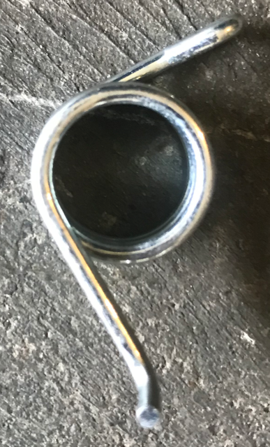
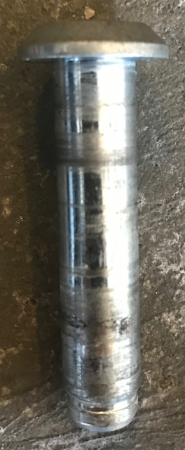
Repair
The footpegs' aluminum casting is relatively brittle, and the pegs tend to break rather than bend.
See Footpeg Replacement.
Reference
"Any pegs made for the 2008-2009 Suzuki RMZ450 should fit the DS,DSR,FX models"
Rider Footpegs
These Footpegs are only installed for the rider, versus Passenger Footpegs.
| Sport Footpegs Installed on S/SR/FXS models. Constructed as a cylindrical smooth-surfaced cast aluminum piece with a corrugated upper surface for some grip. They are spring-loaded. There is a hole at the end of the rider footpegs, with/for feeler stud measuring M6X16 with a DIN 1587 M6 18-8 cap/acorn nut. 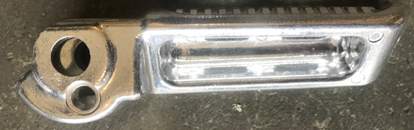 Sport Footpegs underside Dual Sport Footpegs Installed on DS/DSR/FX models. Constructed as a mildly-cleated rough-finish cast aluminum piece with a wide flat surface mounted horizontally. They are spring-loaded. Because of their construction, these actually offer less legroom than the sport footpegs. |
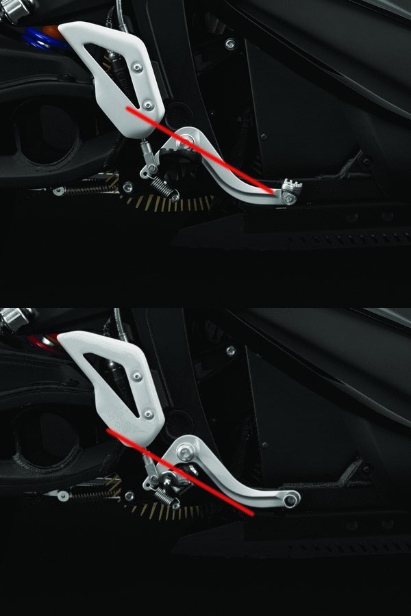 S and DS footpegs compared |
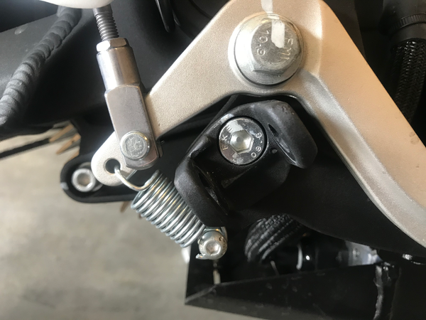 Rider footpegs mounting bracket
Rider Footpeg Removal
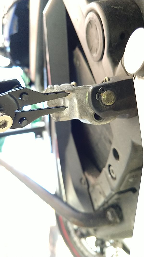 footpeg retaining clip and tool
Tools
- Snap Ring / E-Ring pliers (needlenose pliers are a common if less easy substitute).
- (Optional) 7mm Allen key to remove the clevis bracket from the frame.
Steps
- Gently spread the gap in the retaining E-ring using the pliers until it slides over the end of the pin, and remove it.
This clip is on the lower end of the footpeg retaining pin. 2. Pull the retaining pin up and out.
Hold and pull the pin spring and footpeg as the pin comes out. 3. (Optional) Use the 7mm Allen key to remove the bolt through the clevis bracket that fastens it to the frame.
References
How to Remove Zero Footpegs + Relocation Ideas by NewZeroLand on Youtube
Passenger Footpegs
Passenger footpegs are ergonomically identical to the sport rider footpegs, since passenger geometry requires reduced legroom and a forward foot angle on the rest.
They are not spring-loaded.
They lack the hole for the feeler stud that the rider footpegs use.
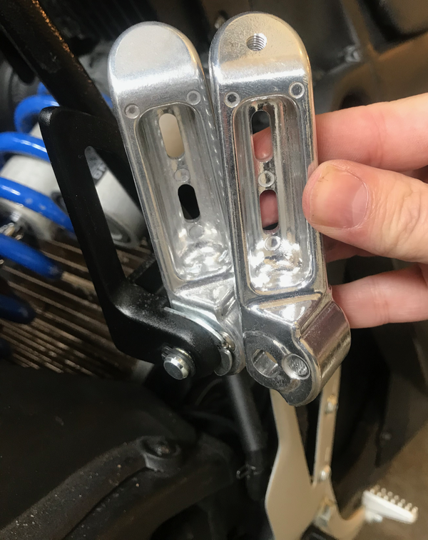 Sport Rider Footpegs vs Passenger Footpegs
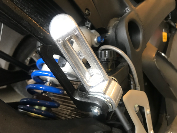 Passenger Footpegs Stowed
Mounting
The passenger footpegs hinge on the passenger footpeg bracket which mounts to the frame.
They use an additional installed pin and custom clip plate to secure the passenger pegs in either the stowed or out position (vertical and horizontal, respectively).
Passenger Footpeg Removal
footpeg retaining clip and tool
Tools
- Snap Ring / E-Ring pliers (needlenose pliers are a common if less easy substitute).
- 13mm hex side or socket wrench (for the bracket).
Steps
- Gently spread the gap in the retaining E-ring using the pliers until it slides over the end of the pin, and remove it.
This clip is on the lower end of the footpeg retaining pin. 2. Pull the retaining pin up and out.
Hold and pull the pin spring and footpeg as the pin comes out. 3. (Optional) Remove the bracket 1. Loosen the upper bolts mounting the footpeg brackets to the frame.
**S-platform:** Reaching these bolts from the rear is easiest since they are on the inside of the frame.
-
Loosen the lower bolts mounting the footpeg brackets to the frame.
S-platform: These face the motor and allow very low overhead.
A side wrench is recommended, and a ratcheting version preferred. 3. Remove the bolts and then the brackets.
References
How to Remove Zero Footpegs + Relocation Ideas by NewZeroLand on Youtube
Seat
The seat is provided in a rider seat section and a passenger seat section.
The passenger seat can be released with the key, revealing a small tray (for tools, perhaps) and hooks for locking a helmet on each side of the tail.
The rider seat can be released by Torx (T15?) bolts that are at the front of the area under the passenger seat.
The SR/S seat differs from the SR/F seat, apparently in being broader and longer especially for the passenger.
Seat Removal
This removes the seat from SDS Platform bikes.
Video Guide
Zero motorcycle - How to remove your seat by Alternative Standard on YouTube
Notes
- Unload any luggage racks before taking the seat off for an extended period of time to avoid stressing the racks.
When luggage racks are installed, the seat bolts are load bearing (or at least damping). - An M8-1.25×55mm socket cap bolt with a 6mm Allen head can be used if the kit bolt is lost.
Tools
- 2015+: T45 Torx wrench (for seat bolts).
- 2013-2014 (with top or side racks): 5mm Allen key (for seat bolts).
Steps
- When luggage racks are installed Remove the top case and/or side cases to ensure the rack is unloaded.
- Remove the M8-1.25×55 seat bolts.
Push the seat down and forward as needed to help ease out the bolts.
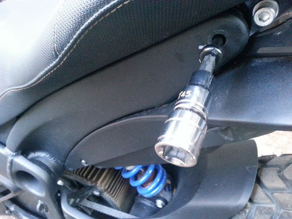 Seat Fasteners
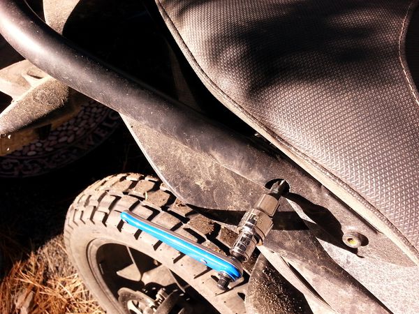 Seat Fasteners with Top Rack Installed
3. Pull the seat back a couple of inches and then upwards.
Seat Install
This installs the SDS Platform models' seat.
Tools
- 2015+: T45 Torx wrench (for seat bolts).
- 2013-2014 (with top or side racks): 5mm Allen key (for seat bolts).
Steps
- When luggage racks are installed Remove the top case and/or side cases to ensure the rack is unloaded.
- Place the seat on the tail slightly to the rear of where it will sit.
Ensure that the pan's horn-shaped catches will slip under the frame's Y-shaped centerpiece pins. 3. Push the seat forward and down to sit in place. 4. Visually align the holes of the seat bracket with the seat bolt holes.
Align the seat's bracket with the frame holes to avoid wear.
Align the seat's tabs between the frame rails to avoid stressing the seat pan and marring the frame.
If the top rack is installed, too, check the alignment of that as well to avoid wear trying to thread the bolts. 5. Insert the seat bolts, gently engaging while checking for cross-threading.
Check for alignment again while the bolt head encounters the seat bracket.
Press down and forward on the seat as needed to help align and tighten the bolts.
Seat Fasteners
Seat Fasteners with Top Rack Installed
6. Tighten the bolt head against the frame surface to hold it in place but do not over-tighten.
7. When luggage racks are installed Re-install the top case and/or side cases.
Panel Material
FST Platform/Bodywork Material
Tank Plastics
FST Platform/Tank Plastics
Tail Plastics
FST Platform/Tail Plastics
Tail Plastics Removal
FST Platform/Tail Plastics Removal
Source: zeromanual.com/wiki/FST_Platform/Unofficial_Service_Manual · Wayback capture of 2025-05-17 · wiki last edited 2 May 2020 00:04. Community-written content from the Unofficial Zero Manual, reproduced for preservation; not written or verified by OpenZero. Links to pages that were not mirrored go to the Wayback Machine.