Charging
The CCU (Meanwell-charger-equipped models only for 2013 and 2014FX) and BMS manage the onboard charger and the battery's contactor to prevent or cut off charging in a number of conditions.
Operation
The contactor makes an audible “click” sound when closing and opening.
- Don't twist the throttle after turning the bike on until you hear that click.
The bike prevents itself from lurching forward if the contactor closes while the throttle is open, but you shouldn't rely on that or find yourself surprised. - Similarly, do not start charging without a closed contactor.
The onboard charger will enable charging mode by CAN bus communications, or keying the bike on can at least close the contactor for drive mode.
Charging mode can be retained through charging port inputs at the signal pins, but they cannot initiate charging mode.
Charging Indications
Indications of charging activity:
External
The dash charging light will flash while charging.
The dash charging light will be solid once fully charged.
The BMS front indicator window shows 4 LEDs.
The number of LEDs lit indicates the SOC level in quarters.
Voltage (verifiable with the mobile app)
Battery voltage will rise with its state of charge while charging from below 20% and then stays relatively constant (easing from 100V to 104V) from 20% to 80% where it starts rising again.
A Zero battery will have a full charge when it has 116V while at rest.
During a charging session, the voltage will dynamically increase by as much as 1V so expect 117V at the end of a full charge until charging stops.
Indications for the Zero battery state of charge while charging may have a significant inaccuracy at high charge rates.
Typically, indicated SoC will lag (lower than) actual SoC towards the upper end of the range (80% - 100%).
Turning the motorcycle off and letting the contactor open and waiting for several seconds should restore charge accuracy.
The BMS historically would thereby reset its method of SoC estimation to a static voltage-based method.
The battery will charge most efficiently between roughly 20% and 80% state of charge, with voltage high enough that current limits allow more power input.
At higher voltages, chargers taper out of concern to maintain battery condition.
Charging Heat
The Zero battery will emit heat above a charging level of 0.4C (4kW for a 4-brick pack), and will naturally cool below that threshold.
Expect several degrees Fahrenheit rise when performing a full charge near a 1C rate.
The cause is best characterized as wikipedia:Internal resistance of the battery, driven by current flow.
The power wasted from this characteristic will be roughly proportional to the square of the current flowing into the battery.
External Inputs
On the SDS Platform, the Onboard Charger is contacts the bottom face of the battery case and will conduct some heat into the battery as it operates.
Discharge Heat
Discharging a battery at a very high rate can also produce heat.
The internal resistance from charging seems to be higher for a given current than the internal resistance from driving/discharge.
High Temperature Guidance
See the hot weather usage recommendations for thorough guidance.
If the battery temperature is already high enough to cause concern about the next charging phase, ride at relatively modest speeds to allow ventilation to cool it faster than discharge heats it up.
Use a battery temperature indication to help understand this.
On-board Charging Port
The onboard charger is connected to an IEC C14 inlet hard-mounted to the lower left side of the frame above the footpeg.
Fasteners
The C14 inlet is fastened to the inside of the frame by 2 tiny M2×7.5 socket head bolts taking a 2.5mm Allen/hex key.
The bolts are positioned above and below the body of the inlet; the lower can be accessed from the front, and the upper from the rear.
The space around the fasteners is very tight, facing the motor, and difficult to see or access.
NOTE: Because of the close proximity to the motor, front sprocket, and other electrical connections, take care not to drop or lose these bolts as you remove them.
Rubber Plug
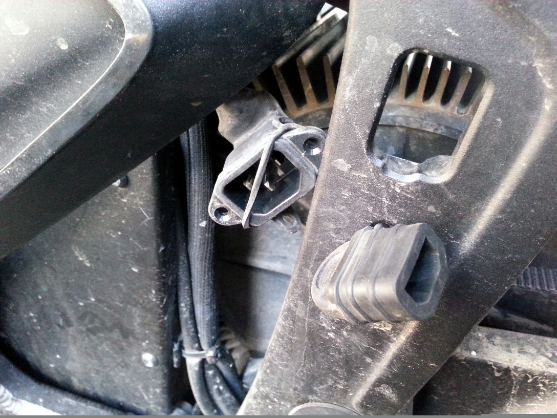
A rubber plug is included to protect the inlet from the elements (which then protects the onboard charger from sparking currents that can degrade it over time).
Keep the rubber plug on when the inlet is not connected to a cord.
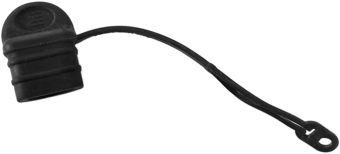
Plug Replacement
- Remove the left pillion footpeg bracket
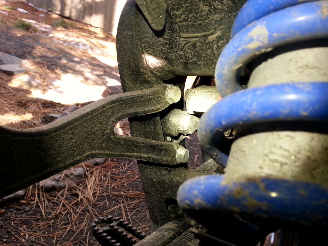
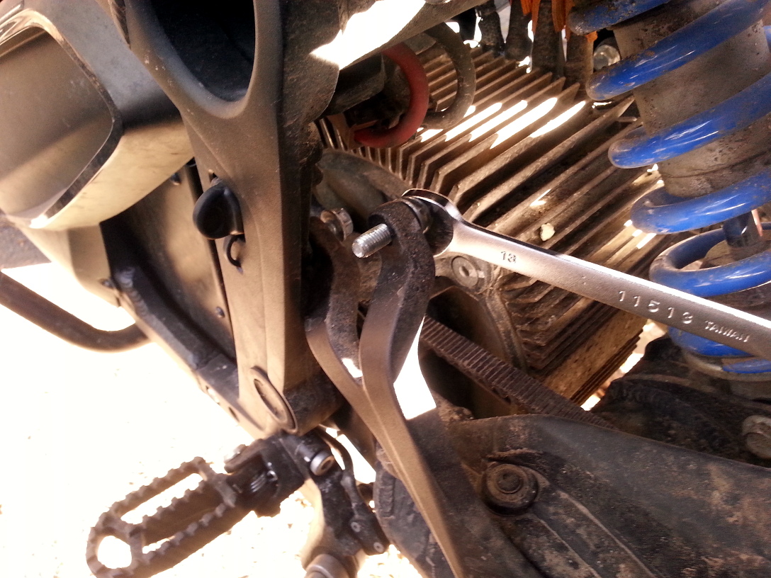 2. Remove the fasteners holding the electrical receptacle
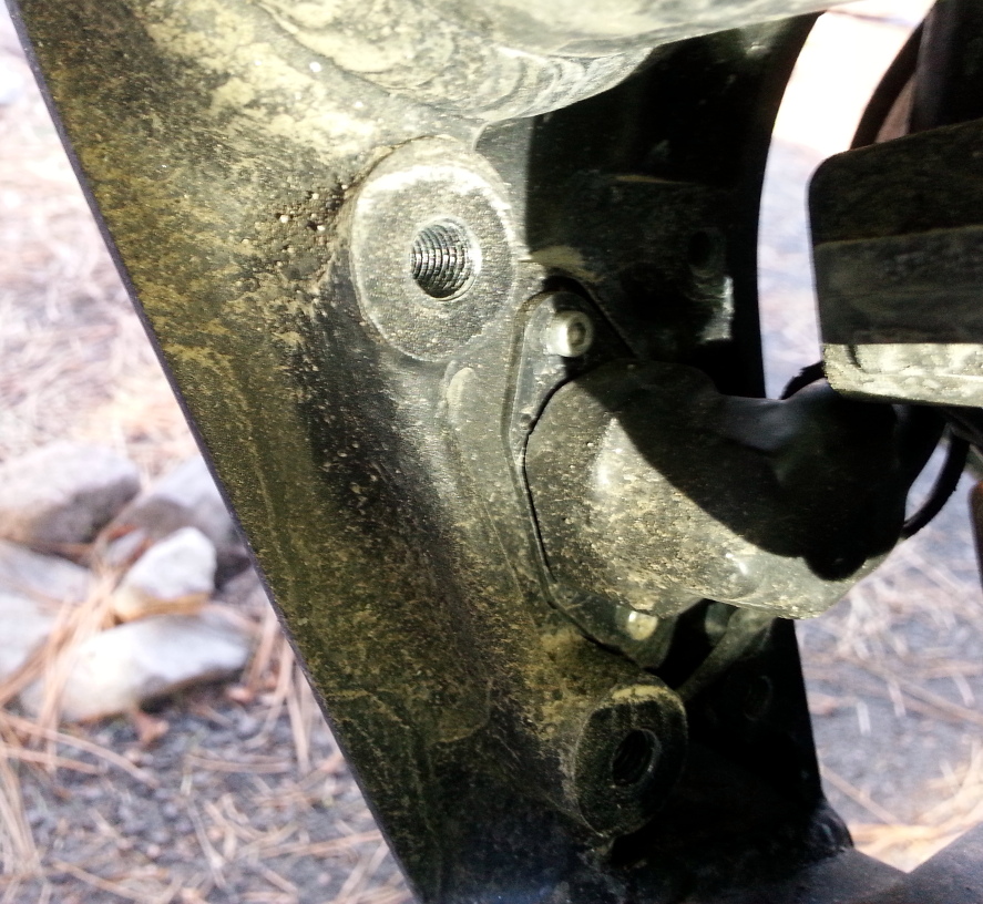
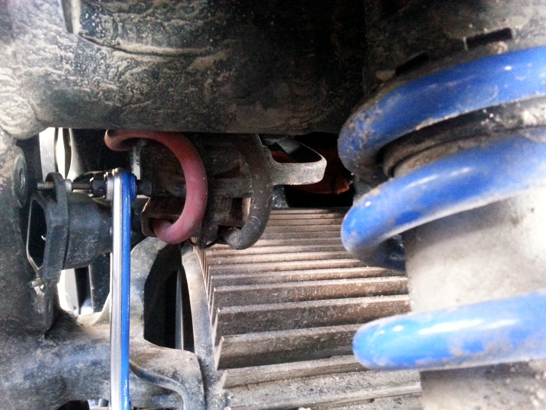 3. You now have access to remove/replace the rubber protective plug
Accessory Charging Port
The Gen2 platform includes a charging circuit terminated by a hard-mounted brown Anderson SBS-75X connector to support OEM and third-party additional chargers.
Input
 Warning: |
Only supply DC power to this port in the battery's normal range, or risk catastrophic damage to the battery. |
All external chargers are switching power supplies that turn AC (or sometimes DC!) power at a wider range of voltages into DC that behaves well with Zero's battery technology and voltage range.
2012 Zero batteries operate in a lower voltage range than 2013+ Zero batteries; chargers for one range of years should never be used on another range of years.
To use
- Remove the rubber boot cover and plug in the charger(s).
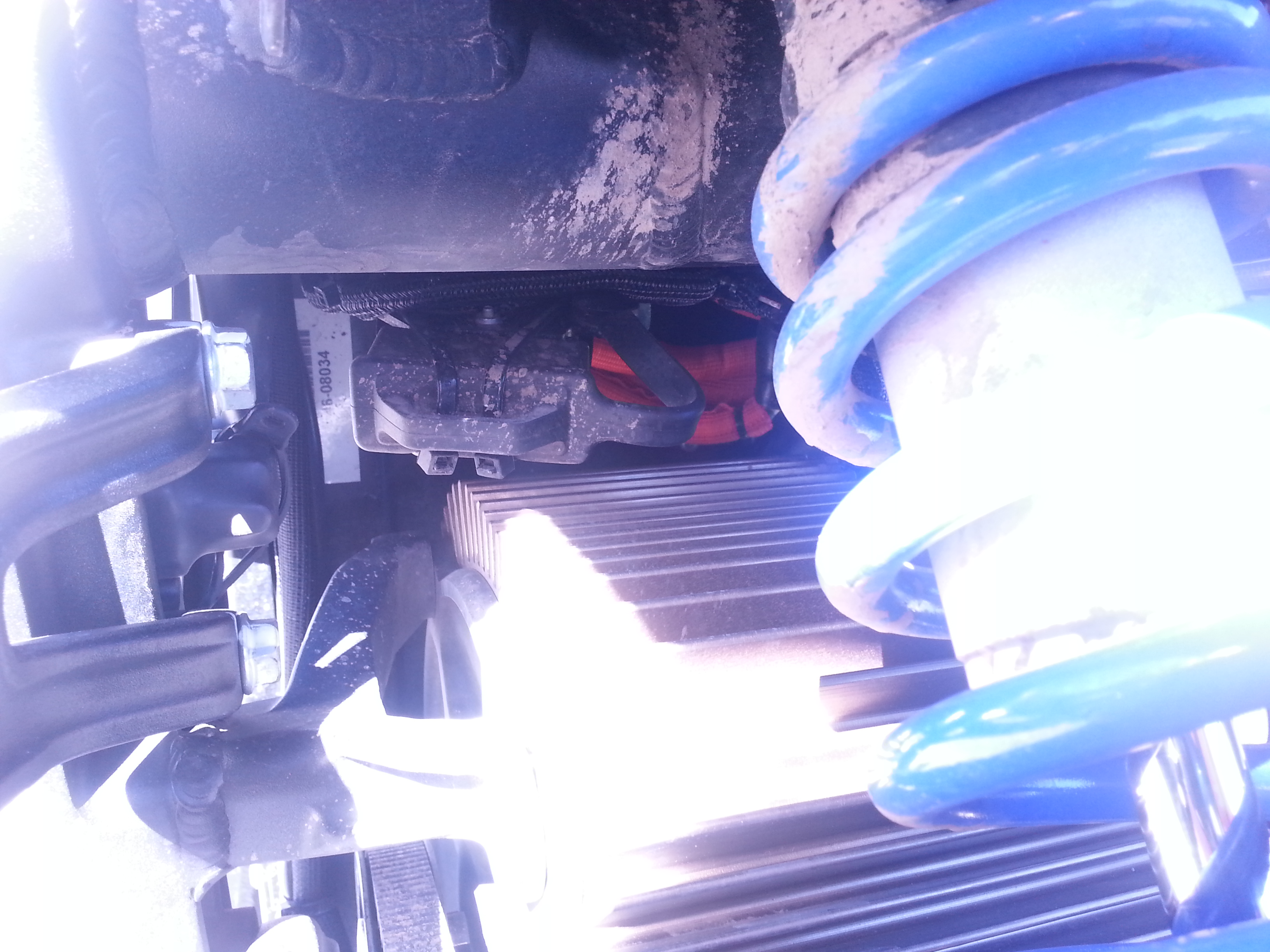
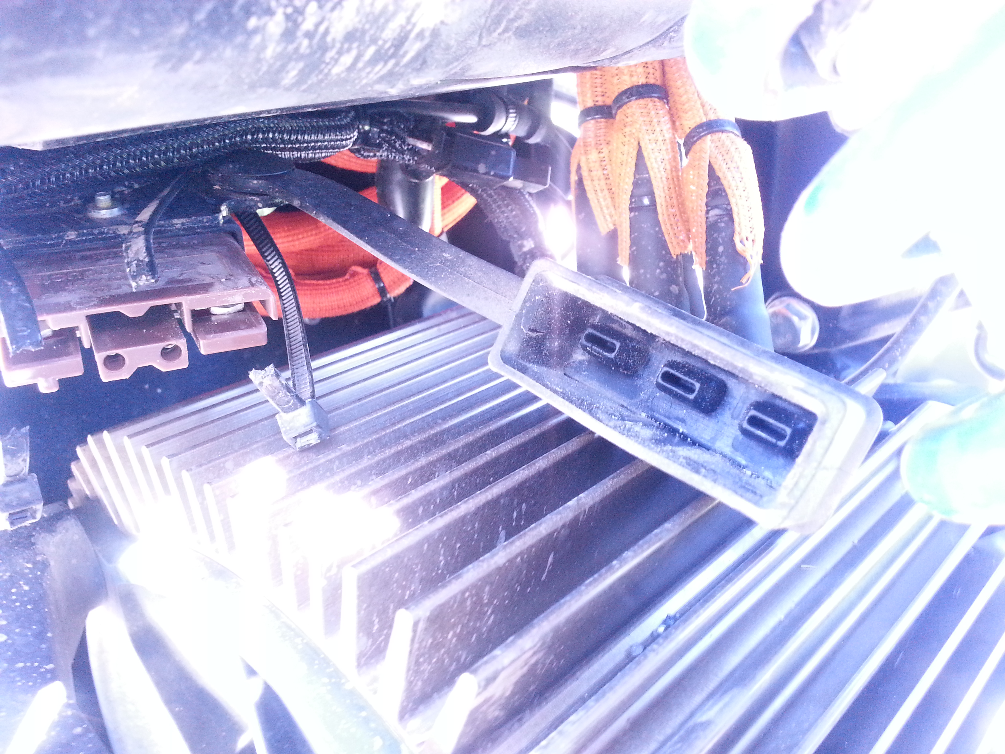
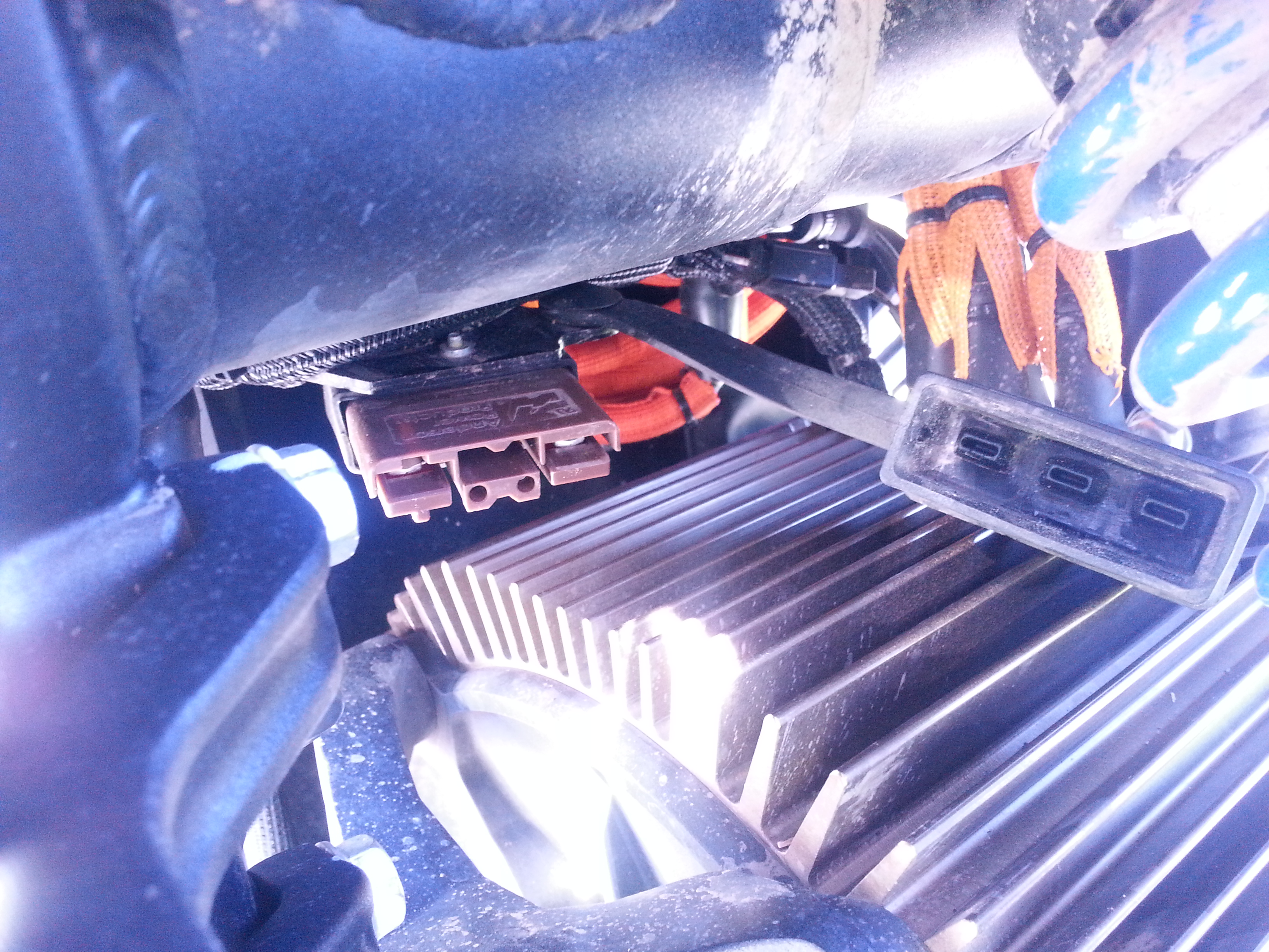
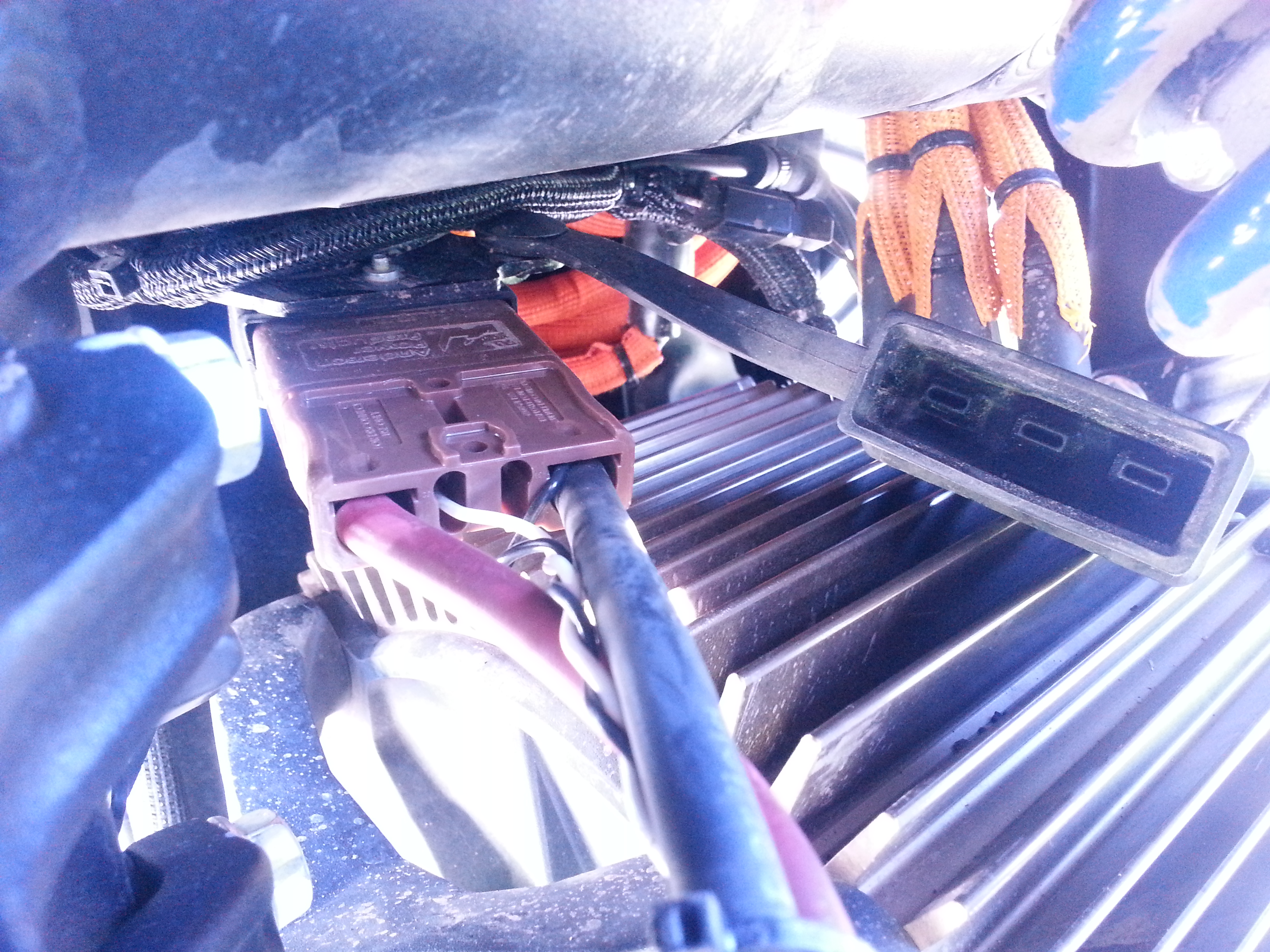
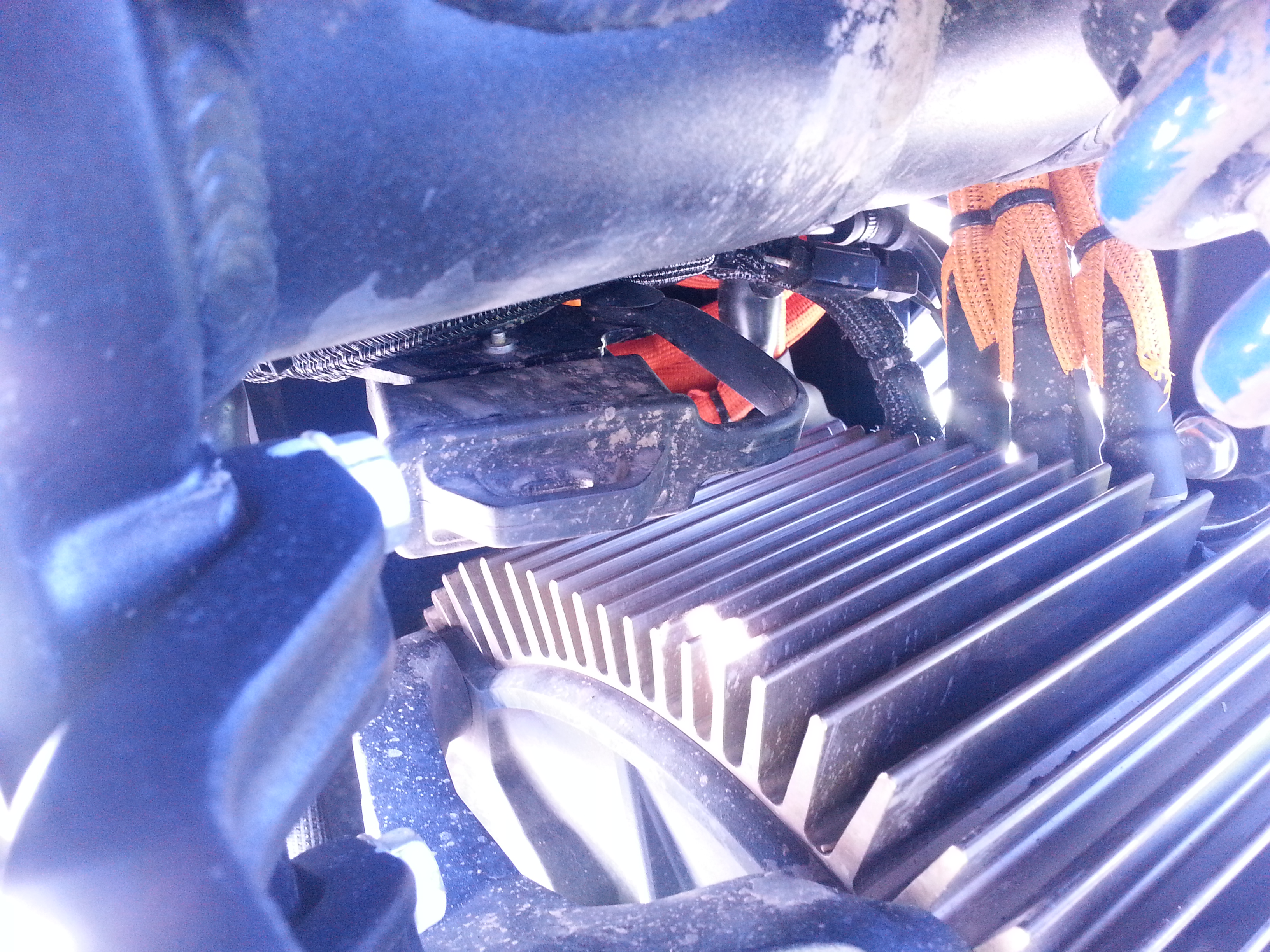
As delivered, the rubber boot cover will be secured with zip ties. Remove them first.
2013 models do not include the rubber boot; it is a good idea to install one to protect the plug over time, though. - Use the onboard charger in conjunction with the accessory charging port to keep the motorcycle in charging mode (allows keying off while charging among other things). - Replace the rubber boot after unplugging the charger(s).
| Platform | Years | Location |
|---|---|---|
| X | 2013+ | Forward of the motor on the right lower side of the frame, under a plastic panel with 5 fasteners. |
| S | 2011-2012 | Right side of the battery. |
| 〃 | 2013 | Above the motor on the right side (opposite the ODB-II port). |
| 〃 | 2014+ | Above the motor on the left side (more accessible than 2013), covered by a rubber boot. |
Location
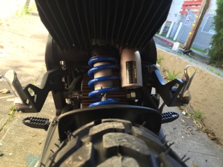
Mounting (SDS Platform)
One or two small H2.5 Allen key socket head bolts run up through the connector's holes into a collared insert on a flanged edge of the board mounting plate.
Detaching (SDS Platform)
- Remove the left lower plastic panel first for access.
- Either:
- Use a very low overhead / right-angle H2.5 Allen key wrench from the left side of the bike ahead of the vertical frame stanchion.
- Pull the board mounting plate up by enough room to fit a right-angle Allen key underneath, between the connector and the motor fins, about an inch or two.
Enable Line
The Anderson SBS-75X connector has two signaling pins which the Gen2 employs in conjunction with a feature of the Zero Quick Charger to indicate charger presence.
The feature is not completely understood, but it operates this way:
- When the contactor is shut, if the enable line detects charger presence, the contactor will remain shut until or unless the enable signal is removed, or a safety limit is detected by the BMS requiring opening the contactor.
- The enable line has no effect if the contactor is open.
Implementing the feature has been performed in various ways.
- See the XMX off-bike charging article for enable pin wire-up or charging Y-cable fabrication for how to combine enable signals safely.
- One minimal implementation joins the two pins in a simple 100kΩ resistive circuit.
Full pack voltage would supply 1mA current to such a circuit at most, so a high-current wire is not needed; just a solid circuit pinned appropriately for the connector with an inline resistor and weather+abrasion+strain-proofing).
| Warning: |
This implementation has not been officially vetted by Zero, and there may be unknown effects operating with such a circuit long-term |
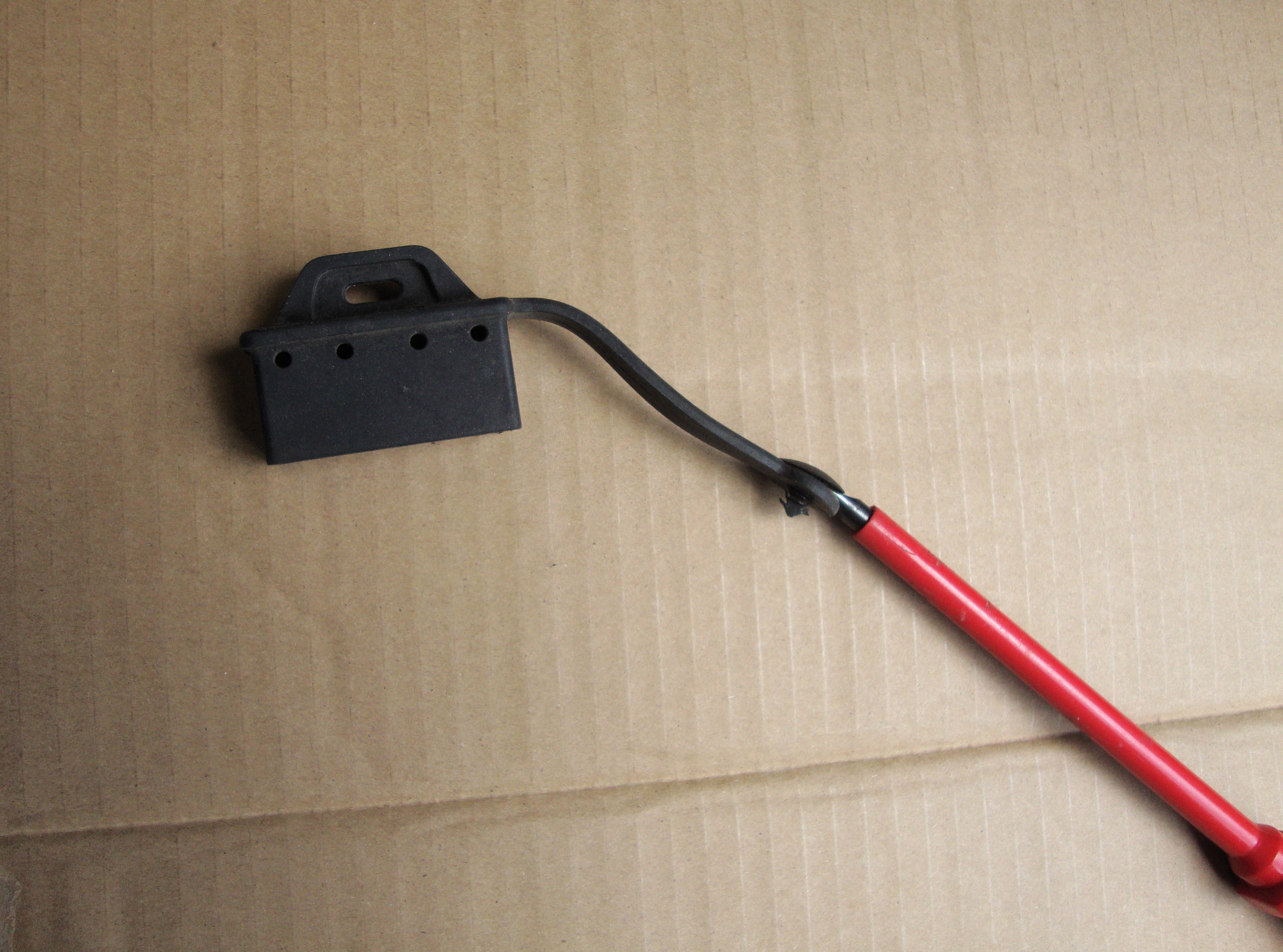
Removing the rubber boot
Only for when you are replacing the Anderson connector permanently with another type/shape of connector.
The rubber boot is held by a nylon "fir tree" plug.
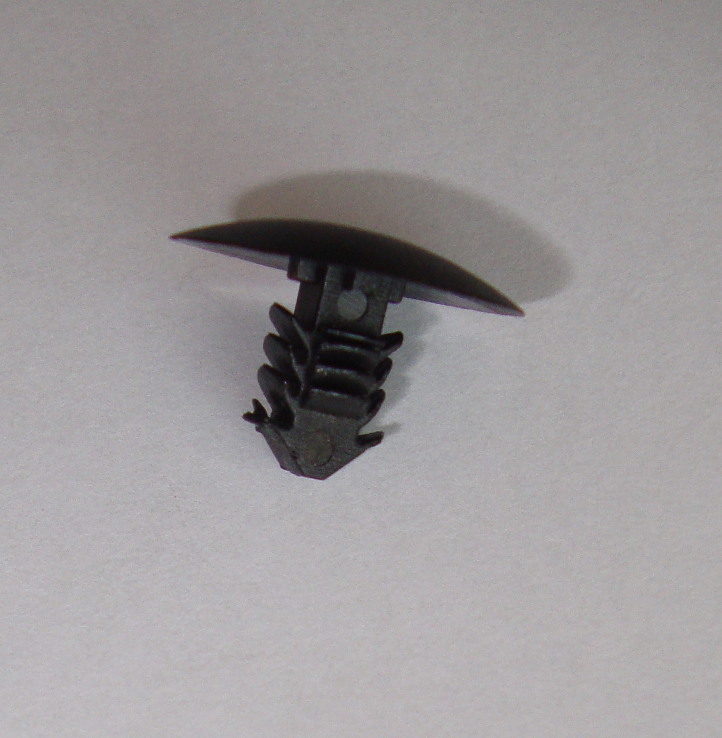
Use a flat tool (screwdriver, nylon pry tool, etc) to wiggle between it and the mounting plate until loose.
After removing, you can install the rubber boot elsewhere using (for example) an M5 bolt and some washers.
Charging Circuit Fuse
The charging circuit has a fuse encapsulated in a cable that protects the battery from charging at too high a rate.
Affected Circuits
- 2013: the charging fuse acts on the accessory charging port, and does not disable the onboard charger.
- 2014+: the fuse acts on the circuit containing both the accessory charging port and the onboard charger but has a much higher limit.
Location
On the right side of the bike under the seat behind the battery, near or under quite a few 12V cable runs.
| Platform | Years | Current Limit (Continuous) | Power Limit (Continuous) | Product |
|---|---|---|---|---|
| X | 2013+ | |||
| S | 2013 | 30A | 3kW | Eaton JJN-30 |
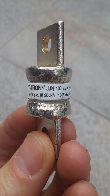
| 〃 | 2014+ | 100A rated, 85A slow limit | 10kW | Eaton JJN-100 |
NOTE
2013 Battery Pack Longevity Recalls
The battery pack replacements performed by the manufacturer due to discovered defects wind up being upgrades to 2015 and then 2016 model year power packs, and seem to include upgraded charging circuits, so those older models will have the higher-rated fuse and work like the newer bikes, charging-wise.
Replacement
| Warning: |
This fuse is not meant to be user-serviceable, and could be very dangerous to replace without the exact same specification. |
The fuse is downstream from the contactor, so if the contactor is open (it should be if you can't charge and the bike is keyed off), it should be de-energized.
Verify this with proper testing equipment.
It's a huge inline fuse within adhesive heat shrink, so it's difficult to extract and replace.
The wires do have ring terminals once you get the fuse out, so you could wire in a fuse breaker. Or if in a pinch just bolt them together.
Fuse Part Investigations
A 2014 SR was found to have an Eaton JJN-100 fuse, a fast-acting fuse rated for 300V and 100A.
Datasheet for the Eaton JJN-100
If the 2014 match is correct, a JJN-30 would seem to be the match for a 2013 Zero (same datasheet as above).
There was supposition of a 60A limit on 2014 motorcycles, implying a TTN-60, but that has not been proven with evidence.
Source: zeromanual.com/wiki/XMX_Platform/Unofficial_Service_Manual · Wayback capture of 2025-09-10 · wiki last edited 4 November 2020 02:21. Community-written content from the Unofficial Zero Manual, reproduced for preservation; not written or verified by OpenZero. Links to pages that were not mirrored go to the Wayback Machine.