Electronic Systems
Instrument Cluster
Until 2014, Zero used branded versions of generic Koso instrument clusters, mapping the fuel level indicator to battery state of charge.
Koso XR-SR
The Koso XR-SR is a generic/whitelabel instrument gauge cluster, used on 2008-2011 model years.
References
Koso RX-1N
The Koso RX-1N is a generic/whitelabel instrument gauge cluster.
For years 2011-2013, Zero's models have a rebadged version as stock.
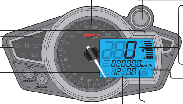 Koso RX-1N (retail)
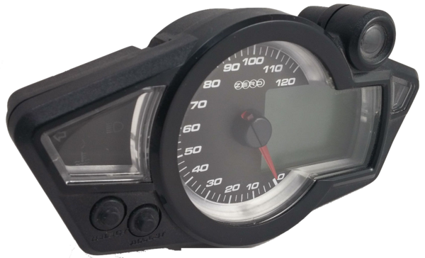 Zero's Koso RX-1N cluster (front)
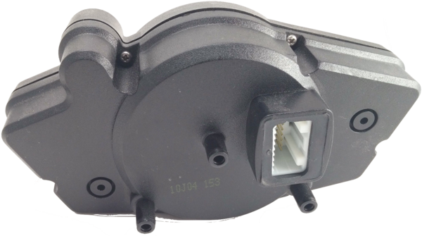 Zero's Koso RX-1N cluster (rear)
References
Features
Zero's RX-1N shows battery level in 11 increments.
It's relatively effective to treat each increment as representing 9% of charge state, and do a little mental math to figure out that each increment could represent 6-12 miles (for say 2013), and work out the remaining range / speed tradeoff from that.
- go slower to get closer to 12 miles of range per increment
- go faster if you can afford to burn off the battery to reach your destination in time.
The Koso instructions linked below show how to operate it.
Speedometer Adjustment Quick How-To
-
Turn on motorcycle.
- Press and hold the Select + Adjust buttons simultaneously for 3 seconds.
-
Use the "adjust" button to increment the digit, and the "select" button to navigate to the next digit.
-
The stock setting (for 2013) is 1972 28-132 2P.
- The previous setting (for 2012?) was 1972 25-128 2P.
Connections
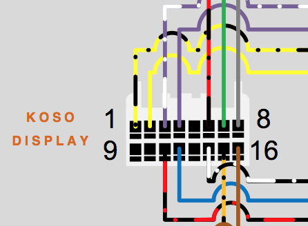
Koso connectors are much simpler than Zero's connectors to its own custom dash.
Interchanging them would be a significant project.
Zero 2014 Instrument Cluster
In 2014, Zero introduced their own LCD instrument cluster AKA "dash" for all models (S and X platforms).
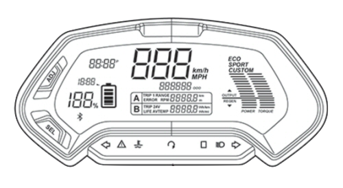 Zero 2014 instrument cluster
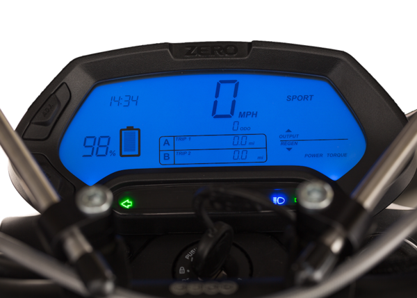 2014 Zero instrument cluster
Changes
The new gauge changed the pin connector and relies on specific CANbus messaging, so there's no simple way to install one on an older model.
It offers an ergonomic advantage that the instrument cluster no longer obstructs access to the keyed ignition and steering lock.
The state of charge reading is now primarily numeric as a two-digit percentage, with a (effectively) continuous bar level reading next to it.
- Disadvantage: no countable number of increments and also making the rider more aware of state of charge calculation nuances.
- Advantage: It's more accurate, and the dash's other functionality (like range and efficiency readouts) easily compensates for remaining inaccuracies.
Zero's Official Owners Manual explains its capabilities pretty well.
| Area | Indicator | Source | Adjustment |
|---|---|---|---|
| Left | Clock | Internal Powered by a non-replaceable battery |
SEL+ADJ |
| 〃 | Time to Charge | MBB | Projected remaining time estimate in hours and minutes. |
| 〃 | SoC | MBB | MBB settings Fuel Gauge Pessimism NOTE: The indicator skips 81,61,41,21, and 1. |
| 〃 | Bluetooth Indicator | 〃 | After key-on or the first minutes of charging Unless/until a mobile device pairs See Unable to Connect and Pairing |
| Center | Speed | 〃 | MBB settings Sprocket Teeth Front Sprocket Teeth Rear Rear Wheel Circum |
| 〃 | Odometer | Stored in the unit's memory | Unalterable If stuck/frozen, the likely cause is that the MBB has misconfigured model information. - Have a dealer examine and correct it, which should propagate an updated reading to this indicator. |
| 〃 | A | MBB | To toggle: 1. Press SEL once so that this blinks. 2. Press ADJ to cycle through: - Trip 1 odometer (resets after a full charge or manually). Units are mi or km. - Range estimate, based on a projection tuned by recent ride history. Units are mi or km. - Error cycling through the Error Codes - RPM motor rotational speed. Units are RPMs. |
| 〃 | B | 〃 | To toggle: 1. Press SEL twice so that this blinks. 2. Press ADJ to cycle through: - Trip 2 odometer (resets only manually). Units are mi or km. - Trip AV average efficiency over Trip 1 as Energy/Distance = Power/Speed. Units are Wh/mi or Wh/km. - Temp motor temperature only. Units are °F or °C. - Trip AV average efficiency over vehicle lifetime as Energy/Distance = Power/Speed. Units are Wh/mi or Wh/km. |
| Right | Drive Mode | 〃 | mode selector switch on right handlebar |
| 〃 | Power | 〃 | Throttle |
| 〃 | Torque | 〃 | 〃 |
| Bottom | Left Turn Signal Indicator | 〃 | Left handlebar turn signal switch |
| 〃 | System Warning Indicator | 〃 | Check System Warning Sequences |
| 〃 | Temperature Warning Indicator | 〃 | Controller, Motor, or Battery Temperatures at Stage 1 |
| 〃 | Check Engine Indicator (2018+) | 〃 | Error Codes triggered permanent torque reduction |
| 〃 | Drive Mode Enabled | 〃 | Green light is: - Solid when contactor shut and cutout disengaged - Blinking when precharging - Disabled/off by cutout or interlock |
| 〃 | ABS Indicator | 〃 | Whether anti-lock braking is operational: - On just after startup before reaching 3mph when the ABS tone rings align fully - Off while riding unless ABS is engaged. - On while riding if ABS is engaged because of a difference between wheel rotational speeds. |
| 〃 | Charging Indicator | 〃 | Green LED is: - Flashing when charging - Solid when full - Off when riding |
| 〃 | High Beam Indicator | 〃 | Left handlebar headlamp switch |
| 〃 | Right Turn Signal Indicator | 〃 | Left handlebar turn signal switch |
Mounting
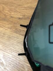
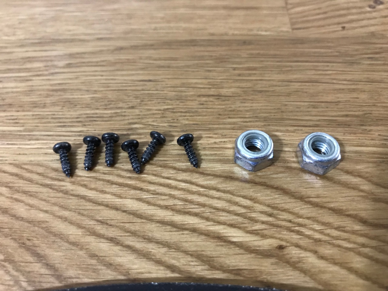
This instrument cluster has two M6 (6mm diameter) threaded rods extending from the rear of the enclosure, captured against the plastic shoulder pieces to the headlamp assembly by two 10mm nylon locknuts.
Remove the display before removing the plastic shoulder pieces, and re-intall the plastic shoulder pieces before re-installing the instrument cluster.
Common Problems
- Clock skew
The internal clock is separate from the MBB clock so can drift over time, often faster by minutes per month or so. - Loss of indication
When these have issues, it has mostly been due to moisture entering the (relatively well-sealed) housing.
This can be disassembled for cleaning but would need re-potting with dielectric grease perhaps when re-assembling and need to be very clean and try inside. - Loss of Clock
When the clock reads 00:00 and will not respond to adjustments, it is likely that its internal battery has failed.
Confirm by observing the indications on startup. If "EEE" appears in the main speedometer readout, the battery is likely dead. - Moisture Ingress
The instrument cluster's operation depends entirely on being perfectly sealed.
Any gaps in its insulation can compromise it eventually.
Diagnostics
Assembly
Enclosure
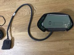
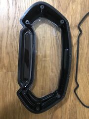
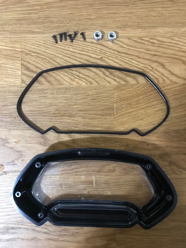 Instrument cluster enclosure front with fasteners
This instrument cluster is enclosed by a plastic housing, with the back half fastened into the front.
The enclosure is fastened by 6 black-finished Philips-head (PH1) machine screws at the rear.
The halves are joined with a rubbery gasket along the edge in a little baffle zone to impede ingress by moisture and dust.
 Warning: |
The seal here appears to be critical to the longevity of the instrument cluster's display and circuits. |
Internals
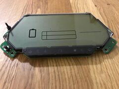
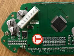
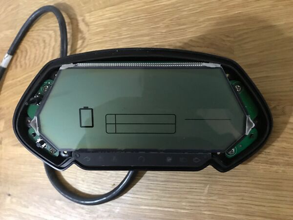 Instrument cluster board uncovered
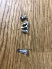
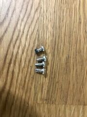
Within the enclosure, the board is fastened to the rear plastic half by 4 Philips-head (PH1) machine screws.
The board's front consists almost entirely of the LCD substrate with no protection - the protective acrylic screen is part of the front half of the plastic enclosure.
| Warning: |
Avoid touching the screen or letting dust fall on it. Clean gently with a lint-free cloth as necessary. |
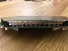
The LCD is connected to the circuitry on the rear of the board by pins along the top edge.
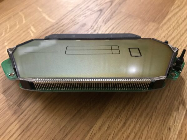 Instrument cluster board LCD drive pins
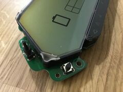
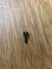
The Select and Adjust buttons trigger micro-buttons on the left side of the board, which have very small plastic extensions linking them to the rubbery buttons.
| Warning: |
Take care when uncovering these buttons not to lose the thin button extensions. |
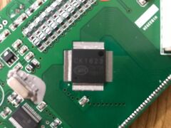
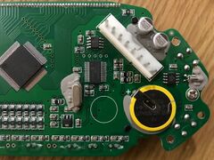
The rear of the board displays the circuitry driving the display.
On the right side of the rear of the board, the internal battery is held.
The battery is a 3V lithium CR2032 cell, which can be replaced with a carefully-chosen cell.
Connections
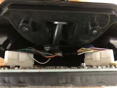
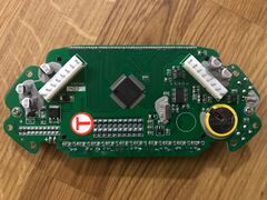
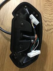
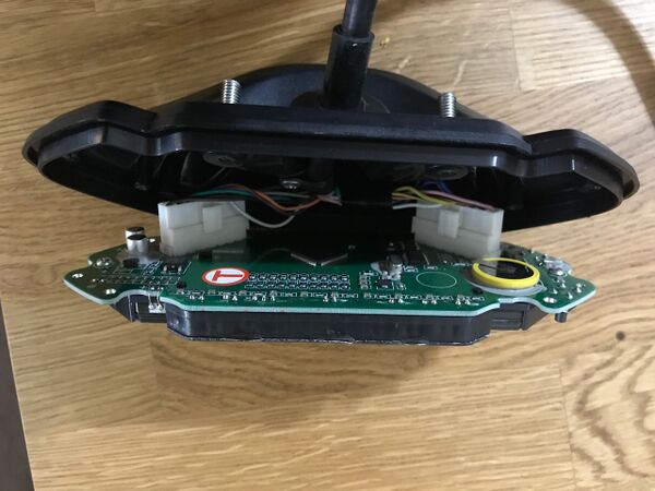 Instrument cluster board connectors
Two connectors at the rear of the board join the circuitry to the signaling interface with the rest of the bike (via CANBus).
The connectors are fastened with a simple clip.
The cable entering the rear of the enclosure is fastened to it by a simple plastic clip and a Philips-head (PH1) machine screw.
Removing the cable should first involve unclipping the board connectors before loosening the screw holding the cable clip.
Charger
How do I move a thread to a different topic? hi all :)
Calex Charger
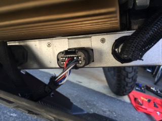
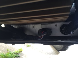
The Calex / GreenWattPower EVC-116-1300 and EVC-116-720 are used as onboard chargers for modern Zero models (2014 onwards except for the 2014FX) and are CANBus-controllable which eliminates the CCU board.
 Calex connections uncovered
 Calex connections
Design
The board is a solid-state switching power supply with a CAN interface.
The aluminum enclosure is well-sealed with over two dozen fasteners.
The enclosure is filled with a solid rubbery potting material.
Reliability
Certain model years (MY14 and MY15) have had onboard charger faults after 900-1200 miles and require replacement under warrantee.
MY16 onward (and MY13 which used Meanwell units) appear to have a lower defect rate.
This appears to be a third-party quality issue with Calex that was reportedly resolved by early 2016, but this is not proven perfectly yet.
720W chargers used on X models appear to be more reliable than 1300W chargers used on S models.
Design Revision
In response to the 2014-2015 reliability difficulties, it seems that the internal board was mainly reworked for lower risk of overheating.
One observation is that the size of the board changed from about ⅓ of the volume of the enclosure to the full area of the enclosure.
Newer revisions seem to have a cube-shaped clip-on ferrite bead EMI filter on the AC input cable (per this EMF thread).
Repair
Because of the solid rubbery potting, repair of anything beyond the connectors is almost totally impractical, especially given the cost of replacement.
The board is designed for blind replacement.
Calex Charger Behavior
Per CANBUS diagnostic reply, the Calex charger operates as a CC/CV mode charger.
- Constant current (CC) mode is the default operational mode.
The charger attempts to deliver a target amount of current to the battery.
This means that the charger's power input is proportional to the battery's voltage at that moment, which rises from low state to the high state of charge, so charging will be slower at low voltages (< 20% SoC). - Maximum allowed battery voltage: 116.4V (Confirmed via charger self-report over CANBUS)
When battery voltage reaches or exceeds this value, the charger enters a constant voltage (CV) mode.
Since the rate of charge dynamically adds voltage to the pack, the taper eases off this addition so there's a stable charge equilibrium at the end.
Tapering behavior is observed to reduce output current in increments of 1A and typically starts at 12A. - Current taper cutoff: 10A (Confirmed via charger self-report over CANBUS)
The charger will cut to 0 output rather than taper below this value. - Maximum allowed current: 65.535 A (Confirmed via charger self-report over CANBUS)
This is a meaningless binary value.
Overcharge Protection
The charger is limited by the manufacturer to a range that matches Zero's battery safe range.
The charger is connected to external AC sources and is therefore a vulnerable component while plugged in.
Per Re: Change to Charging - Leaving Bike Plugged In
- The charger is an isolated power supply with suppressors on the input.
- So, if a surge were big enough, the suppressors could fail short.
- Then the circuit breaker should fail after that.
- The BMS and the rest of the bike is completely isolated from the charger, so there's no current path to them.
This is why some people on this forum report their charger is dead, but the bike is fine, and there wasn't any fire. Most of the time Zero, replaces the onboard charger for them.
Worst-case scenario
- BMS unresponsive
- MBB unresponsive
- Contactor welded
- Charger outputs more than 117.6V
In the event of all these holding (extremely unlikely), there is some risk of a fire.
This is probably why Zero asks you to check on the bike every 72 hours to make sure the bike is still responding and the BMS is still alive.
Meanwell Charger
The Meanwell HLG-320H-54A power supplies are used as onboard chargers for early Gen2 Zero models (2013 and the 2014FX) and are directed by the CCU board since they lack a CANBus integration.
Configuration
- For SDS Platform models, 4 chargers are wired 2s2p for 1.3kW total.
If any power supply unit fails, the charger should drop to half its output capacity (whether by blowing a fuse or faulting open internally). - For XMX Platform models, 2 chargers are wired in serise (2s1p) for 650W total.
If either power supply unit fails, the charger will fail to produce output entirely.
Repair
- See Half of a charger fail.
- It is possible to replace only the dead charger if you have one.
You'll need big crimping tools and shrinking sleeves.
Zero sends the full pack of four chargers.
Meanwell Charger Behavior
These chargers do not interact over CANBus messaging, so just operate in a preset way in CC-CV mode, although the CCU also has some control over it to implement battery protections.
Clicking Sound
There is a known issue, per Clicking sound when plugged-in, that the Meanwells sometimes make a repeated clicking sound.
It seems to happen generally in the cold.
This symptom does not seem to precede an equipment failure, and should go away once charging is complete.
Charger Operation
Mainly, the charger is the most routine bike maintenance and you just plug it in and can forget about it.
When to Charge
Per Zero's recommendation, the battery state of charge is ideally kept between 30% and 70%.
- Always plug in when the SoC is below 30%.
- Leave it plugged in to reach 100% and improve cel balance if you are planning to ride the bike in the next few days.
- You can unplug the bike when it reaches 70% if the bike will not be ridden sooner than a few days, or if your next ride will not require more charge.
This keeps the battery in a healthier state and improves battery lifetime beyond the warranty.
What to Watch For
When plugging in, expect:
- The contactor to close with a click or remain closed.
- The dash charging indicator to begin blinking green.
- After a few seconds, (2014+ models) the charge time indicator should display a number of hours and minutes until fully charged.
This indicator helps predict when a desired SoC can be anticipated, with a little math.
Trouble Indications
- Spark at the plug when connecting.
- Heat from the plug.
- No charging dash indicator.
- Circuit breaker trips.
Reliability Tips
There is a growing consensus that the Calex charger's limited cooling capacity can lead to damage over time if it's operated repeatedly at the high end of its rated band.
To minimize risk of a charger fault or component burnout, avoid operating it while the battery is hot and still cooling, and address any heating or sparking at the plug.
Check the Common Charging Problems section regarding the plug and cord.
Basic suggestions:
- After an intense ride in the heat with the battery temperature high, wait for a couple of hours until the temperature is lower.
- Keep the inlet covered when not in use.
- Use contact cleaner on the inlet periodically (once per month) or whenever the charging cord plug warms up significantly during charging.
- Minimize strain and load on the charging cord.
- Unplug the cord and cover the inlet when not in use.
Ground fault circuit isolation (GFCI or GFI) enabled outlets often trip when using the Zero onboard charger, relating to how AC phases are wired to a single or multiple outlets.
If this happens regularly, it is reasonable to break off the grounding pin from your charging cord, or, better yet, get a cheater (three prong to two prong) "cheater" plug.
Charger Power Cord
The charging cord is a 10-ft 14AWG cord with a NEMA 5-15P (US) to IEC320 C13 output plug rated for 15A.
Zero specifies that any extension cord be at least the above specification, and 15A continuous rating is important to look for.
Demand
- The S-Platform onboard charger draws 11-12A at 120V AC (and half the amps at ~220V).
- The X-Platform onboard charger draws 7A at 120V AC (and half the amps at ~220V).
Tips
- When in doubt, prefer a thicker gauge cord, a shorter length, and a sturdier plug.
- Do not let a charge cord sit coiled up, particularly in a container; make sure that any heat produced is not confined near the cord for any reason.
- Plugging into a 220V outlet will reduce the current to the onboard charger by half, so is one way to drastically minimize risk to any cords.
Replacements
See Spare Onboard Charger Power Cables
Charger Connections
Calex Charger Connections
AC input is an IEC-60320 C13 inlet.
DC output is an Anderson SBS50-BRN, but it seems to be a narrower pin pitch with no center data pin set.
CANbus signal interface is a JAE MX23A18NF1 connector (applies to the Calex, not the Mean Wells!)
| Pin | Function |
|---|---|
| 4 | CAN ground |
| 5 | CAN +5V power |
| 6 | CAN Dominant Low |
| 7 | CAN Dominant High |
| 10 | ob_charger_attached_n [charger_attached] |
| 11 | ob_charger_attached_n [charger_attached] |
| 12 | charger_en_0 [charger_en_n] |
| 13 | ob_charger_ref_0 [charger_gnd_ref] |
CANbus wiring
Adapted from an examination of the wiring on a 2014 SR: Onboard charger wiring for 2014 and 2015+ for the Calex.
When the onboard charger is plugged in and powered on the onboard charger pushes:
- 5V and 48mA through the Charger attached Pin #11.
- 5V and 26mA through the Charger enabled Pin #12.
The 5V ground reference is Pin #13 which is battery negative.
With this knowledge, another onboard charger solution can be wired to function as follows:
- Run a separate circuit that when triggered pushes 5V ~50mA through pin#11 (attached charger) with the other end of the 5V circuit connected to the battery negative pin #13.
- When this is triggered, the bike shows the battery state of charge % and charge time remaining, closes the contactor and allows charging - through the accessory charging port, the onboard charger port or via the Sevcon battery terminals for high power charging.
- Upon completion of charging, the 5V can be switched off and the charge level and time remaining switch off and the contactor opens just as with the onboard charger.
- The bike can be keyed on and ridden away as normal.
Using this method there is no need to leave the bike on when charging via the accessory charging port or the controller battery-side cables, or if you are using the accessory charging port without triggering the auxiliary pin on the accessory charging port's Anderson SBS75XBRN.
NOTE
For 2015 onwards, the charger install uses additional wiring which may have a different approach using CAN signals, so it may require a different approach.
Charger Replacement
Since some generations of Calex chargers seem to develop faults relatively often, being able to replace a charger on one's own might save someone a lot of grief who doesn't live near a dealer.
Video Guide
How to Remove the Zero's Onboard Charger by NewZeroLand on YouTube shows very clearly how to remove the charger from his Zero SR.
Notes
Adapted from these instructions.
Possibly JAE MX23A18NF1 or MX23A18NF3 for harness connection MX23A18SF1 (datasheet via Mouser)
Charging enable hack (by EMF user Liveforphysics)
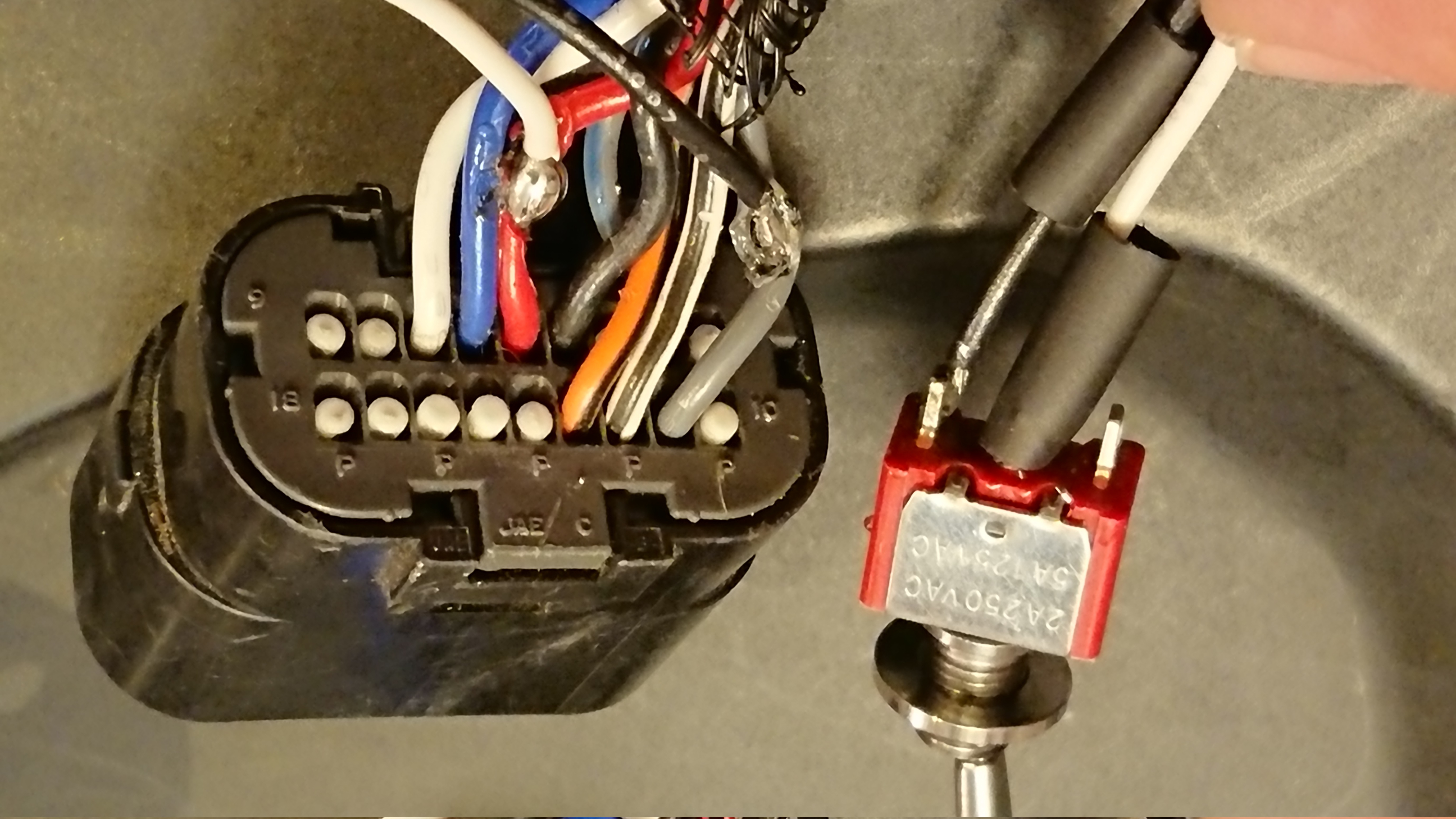 Zero Charger Enable At Harness
Tools
- 3mm Allen key.
Steps
- Unplug the motorcycle, and key it off. Wait for at least 10 minutes to ensure any residual charge has dissipated.
- Remove the lower plastics.
- Belly Pan Removal
Unbolt the belly pan (2 rows of 4 3mm Allen head bolts on each side of the pan, and 2 smaller bolts) and remove it. 4. Unplug the wiring at the rear of the charger area.
There are three plugs (looking left to right at the rear of the charger):
- One on the AC end of things that's bolted to the bike (your charge plug)
- The comms connector (enable signal, CAN comms etc...)
- One plug on the DC side that goes up to the charge wiring harness.
-
The comms plug just has a tab; push in the tab and pull that one out.
Both of the other plugs are really difficult. 2. Removing the DC plug.
The plug is an Anderson SBS50-BRN, but it seems to be a narrower pin pitch with no center data pin set.
The DC plug is located in front of the motor against the back side of the battery on the bike's right. 3. The cables are tucked up between the battery and a frame member, so cut the zip ties (including the zip tie holding the plugs together) and pull the plastic zip-tie mount clips on the lower half of the cable going to the charger. 4. Pull down on the charger side of the connector from the bottom while pulling up on the top connector.
Sometimes this requires a "flesh donation" to the motor, so covering the motor with a rag would be smart. 5. Pull the terminals out of the plug housing (see Anderson disassembly), and pull it down thru the hole between the motor and frame. 6. Removing the AC plug.
It loops up under the seat and is zip tied on in a handful of places.
There are two small bolts on the backside that are difficult to reach, so use a decent set of hex drivers with handles. 7. There is a fuse holder plug that connects the ground to (somewhere...).
Squeeze some tabs to get the green locking piece out.
Then squeeze more tabs to get the plug apart. 5. Now with the cables out, use the 3mm Allen key to loosen (but not remove) the 6 bolts on the tabs holding it up. 6. Remove the charger to the side (recommend the right side) by removing the 3 bolts on the side intended for removal.
On removing the last bolt, support the charger so it doesn't fall out, and carry it to the ground or elsewhere. 7. Remove the remaining 3 bolts using the 3mm Allen key if not installing a new charger.
Assembly
- Assembly is the reverse of disassembly! Really.
Suggestion
You can extended the DC wires on the replacement Calex charger, and put the plug set sideways, and up higher to make it easier to get at.
Main Bike Board
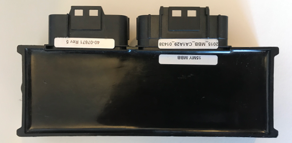 2016 Zero MBB Front
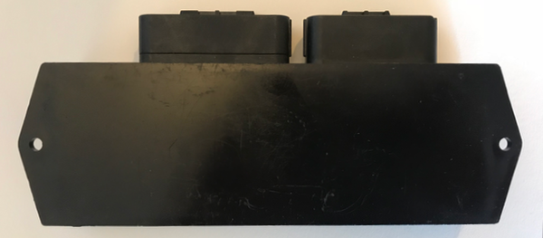 2016 Zero MBB Back
The Main Bike Board (MBB) controls the overall system, implements safety interlocks, and directs the controller.
It is also the entry point for configuring these systems, performing diagnostics, and examining operational events.
When referring to "the firmware", or "the logs", people are referring to this board primarily, and possibly the BMS.
It is enclosed within a fully-potted plastic-like container with multi-pin connectors along the top side.
Location (S Platform)
Below the front area of the seat under cable runs.
It is located aft of (and above) the DC-DC 12V Converter with a bracket sandwiched between them.
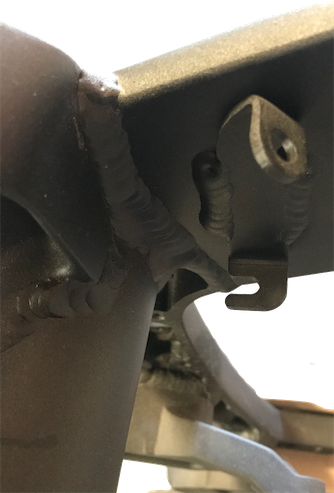 Board Plate Mounting Bracket (Left)
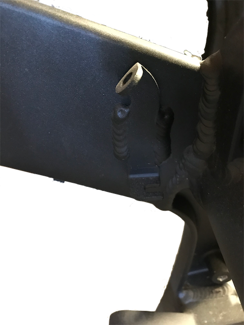 Board Plate Mounting Bracket (Right)
Location (X Platform)
Below the front modular battery (or front half of a longbrick battery) in the triangular bay above the controller.
Mounting (S Platform)
Two socket head bolts with washers fasten the enclosure to a vertical plate.
The bolts enter the plate in the forward direction but offer very limited clearance for manipulating them.
NOTE: on the right, the cables from the controller to the motor run past.
A very small angled 3mm Allen Key wrench is best for unmounting the board.
When using the OBD2 port, the board's application firmware supplies the interactive console.
Playing with the 2012 MBB shows Doctorbass' transcript using 2012 firmware.
- 2013 models' interface differs quite a bit from this but the general logic and experience are the same.
Protections
The board appears to be permanently sealed and potted within the enclosure to protect it from dust and a certain amount of moisture ingress.
Interlock Troubleshooting
Use careful electrical isolation measures when troubleshooting electrical switches used as inputs for interlocks enforced by the firmware.
Replacement
The board must have its firmware setup specific to the bike in question.
Major firmware difference exist across model years such that the firmware binary in question must be selected to prevent major problems on replacement.
- NOTE: Apparently only the manufacturer can perform this provisioning (probably imaging the base kernel, userland, and application-container management).
A dealer must select the correct and latest applicable application firmware to apply to the bike per its basic parameters:
- Year
- Model
- Battery configuration
Information from the bike's VIN is necessary to select the right programming by the dealer or manufacturer.
This information may not be sufficient, if it requires coding in the presence of a Power Tank or Charge Tank.
The board settings require model information to be set per above, and the BMS must agree about this information.
Main Bike Board Limitations
The board design is very modest and seems to prioritize light weight and simplicity over robustness.
Take as much care as possible when troubleshooting in and around this module.
A professional-grade application of dielectric grease around the connectors seems advisable.
- NOTE: Ensure that the entire connector and pins are clean and dry before applying.
Performance and Lockup
The board communicates with the bike's other systems via CAN Bus, which is a 2-wire Multi-master bus.
- This means that multiple nodes on the bus must initiate a transfer.
The board also has limited memory, I/O dispatching, and computational performance.
- So, it can get clogged with requests for data outside its designed parameters.
- So, running any telemetry while in drive mode through the OBD-II serial console or using the Bluetooth transmitter will meaningfully increase the load on the board.
In some cases prevent it from acting on rider inputs, including safety interlocks like the cutout switch or kickstand interlocks.
Reportedly, 2017 and newer models have increased performance and doubled memory capacity.
- This enables an onboard upgrade with an atomic swap of versions by holding new and old firmware versions simultaneously.
- There's no known means of using these in older models.
Electrical Vulnerability
The circuits connected to the pins seem to lack significant protection against shorting faults, which could be a source of breakages while dealing with connected systems.
OBD-II Serial Output
The use of the non-standard OBD-II port most easily draws power from a very limited internal circuit.
The OBD-II port as a result is typically not usable over a long cable without an external power supply and good quality connections.
Main Bike Board Connections
The board has a 34-pin and 40-pin connector exposed through the top of the enclosure, making them relatively accessible and a way to identify the component.
Both are made by JAE Electronics.
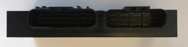 2016 Zero MBB Top
| Connector | Harness-side | MBB-side | Notes |
|---|---|---|---|
| 34-pin connector "MBB 1" | JAE Electronics MX23A34SF1 | JAE Electronics MX34A34NF1. | 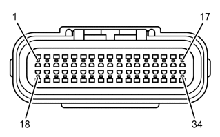 Harness-side pinout; MBB side mirrored 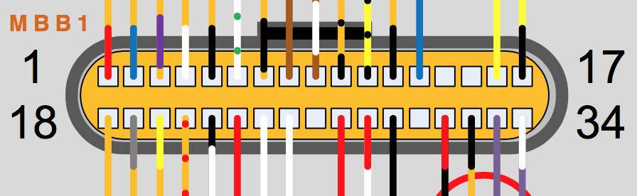 2013 MBB 1 connector Wiring Diagram image |
| 40-pin connector "MBB 2" | JAE Electronics MX23A40SF1 | JAE Electronics MX34A40NF1 | 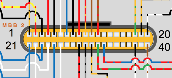 2013 MBB 2 connector Wiring Diagram image |
| Component | Function | Wire | MBB Pin | Role |
|---|---|---|---|---|
| Kickstand Switch | Safety Interlock | Red (2013) 20AWG | 27 | Colors are different for 2016 models: |
| 〃 | 〃 | Orange (2013) (black) 20AWG | 12 | Blue (5v power), Pinkish Red (measure signal TODO), Black. Do not short these directly. That is not how you bypass. |
| 〃 | 〃 | Yellow (2013) (black) 20AWG | 11 | Kickstand Switch |
| Kill Switch | Safety Interlock | Red 20AWG | 23 | |
| 〃 | 〃 | White 20AWG | 24 |
| Component | Function | Wire | MBB Pin | Function | Notes |
|---|---|---|---|---|---|
| DC-DC Converter | Enable Signal | Orange (Red) 18AWG | 21 (2013) 20 (2015) |
Charging Control Unit
The Charging Control Unit (CCU) on Meanwell-charger-equipped models (all 2013 and the 2014FX) collects battery temperature sensor data, battery voltage, and charger DC voltage to decide on whether to open or close the contactor. It also manages the Meanwell onboard charger which has no CANBus connection or programmability, so when the programmable Calex charger was introduced, the CCU's functions were moved to direct BMS/MBB management.
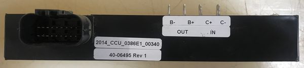 CCU top
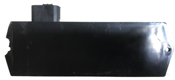 CCU back
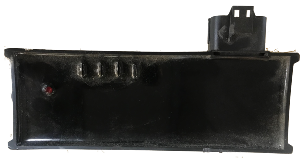 CCU front
Connectors
CCU 18-pin connector: JAE Electronics MX23A18SF1
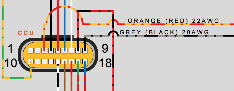
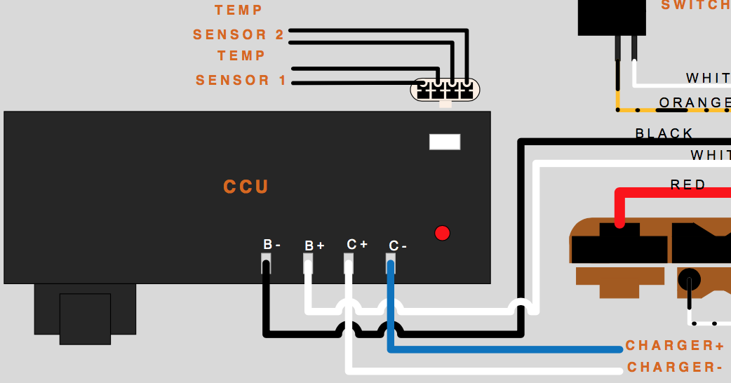
TODO
more from Burton's post here: Re: 2013 S 11.4 quick charger build
The contactor protects the battery against faults. It is analogous to a circuit breaker. The CCU directs it.
2012-2013 models exhibited behavior where the BMS in certain situations yielded a "contactor welded shut" condition that require dealer servicing. Later model years fail more safely (open).
2014+ models do not have a CCU, and the BMS directly controls the contactor and onboard charger.
Location
Under the seat in front of the MBB with the connections mounted on top.
Limits
The CCU terminals are not designed for high amperage currents. Presumably, anything above the 2013's intended 30A charging limit could damage the CCU or trigger the contactor opening.
| Warning: |
This is always energized. Any exposure of this at any time will risk direct contact with battery terminals that could result in injury or equipment damage. DO NOT UNCOVER this without professional-level care! |
If you are in a remote location, and have trouble with a contactor unit not closing without any indication of a particular condition that interlocks it in the BMS, a little mild mechanical agitation (while the vehicle is keyed off) against the top surface with a rubber mallet might loosen it.
DC-DC 12V converter
The DC-DC 12V converter is a solid state switching power DC step-down converter designed to produce low voltage DC power from the pack voltage.
The converters mentioned here are used on Gen2 and Gen3 models.
| Years | Platform | Manufacturer | Model | Replacement Options |
|---|---|---|---|---|
| 2013-2014 | S and X | Sevcon | Sevcon DC-DC 300W converter | OEM or via Thunderstruck Motors - NOTE: Select the 300W model! connector hardware is an extra |
| 2015+ | 〃 | 〃 | Sevcon DC-DC 500W converter | OEM or via Thunderstruck Motors - NOTE: Select the 500W model! connector hardware is an extra |
Appearance
It's about the size of a long box of soap with a black surface, but for 2013-2014 models will be covered entirely with Nashua aluminum ducting tape, so will appear silver.
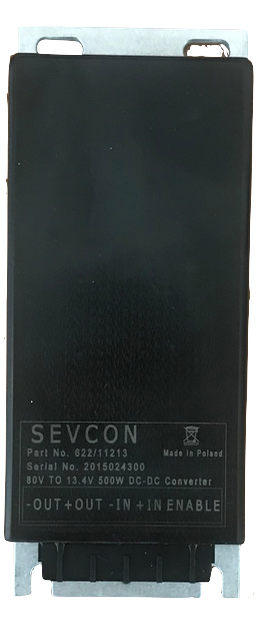 500W Sevcon DC-DC converter - top |
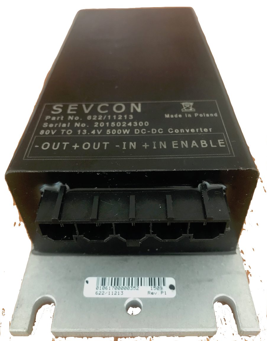 500W Sevcon DC-DC converter - connector 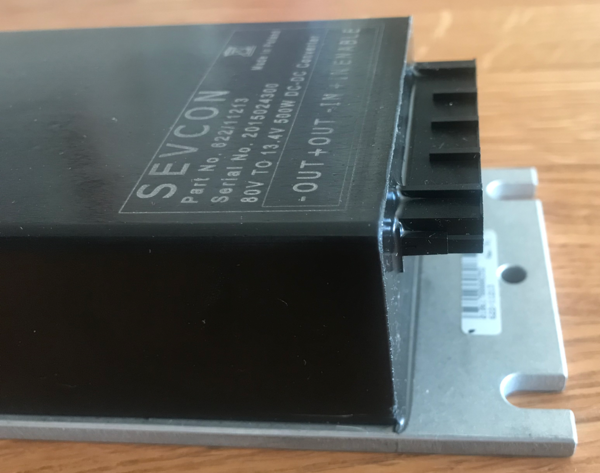 500W Sevcon DC-DC converter - connector side |
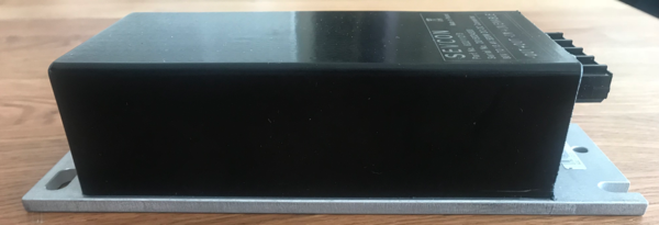 500W Sevcon DC-DC converter - side 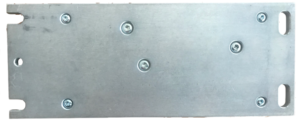 500W Sevcon DC-DC converter - backplate (upside down) 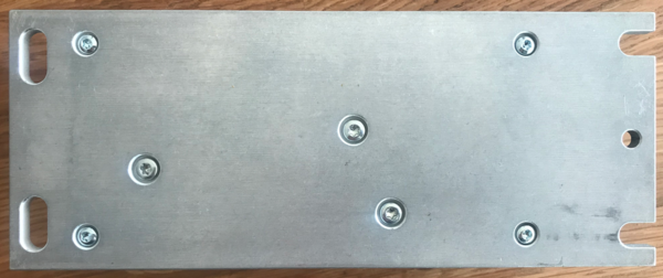 500W Sevcon DC-DC converter - backplate (as installed) |
SDS Platform Location
Below the front of the seat under cable runs, between the MBB (separated by a bracket) and the back of the battery frame area.
Quick and dirty illustrative video of how to find and access the converter
XMX Platform Location
Below the removable battery compartment. See our FX teardown layout guide.
FST Platform Location
Inside the tank, on the right of the bin, on the board mounting plate.
Protections
- Ingress: IP67
- Short circuit overload
- Reverse polarity
- Fully isolated
- Can parallel with diode safeguard
Mounting
The Sevcon 500W DC-DC converter is mounted to its own baseplate via 4 Torx T10 cap head screws and there are 3 additional Torx T15 cap head screws in the middle.
The Sevcon baseplate is then bolted to Zero's board mounting plate with 4 10mm hex head bolts which have 6mm outer diameter, 16mm length, and 1mm pitch.
Removal
- Remove the board mounting plate.
- Remove the converter from the board using a 10mm hex socket wrench.
- Disconnect the connector if appropriate.
Installation
- Attach the converter to the board mounting plate with a 10mm hex socket wrench.
- Install the board mounting plate with the converter back into the bike.
Connections
There is a 5-pin connector controlling the converter, facing the left as installed on the bike, connected as follows:
| Pin | Function | Measurement | Component | Years | Wire | MBB Pin | Illustration |
|---|---|---|---|---|---|---|---|
| 1 | Enable signal | Battery voltage when key is on | MBB | 2013 | Orange (Red) 18AWG | 21 | 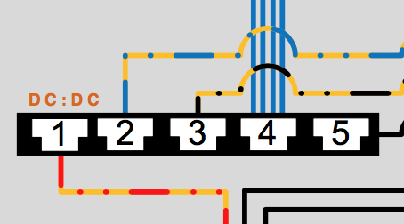 |
| 〃 | 〃 | 〃 | 〃 | 2015 | 〃 | 20 | 〃 |
| 2 | Input (Positive) | 116V | Battery | 2013 | Orange (Blue) 16AWG | 7 | 〃 |
| 3 | Input (Negative) | 〃 | 〃 | 2013 | Orange (Black) 20AWG | 5 | 〃 |
| 4 | Output (Positive) | 13.5V | Fuse Block | 2013 | Blue (16AWG, 14AWG) wires | 〃 | |
| 5 | Output (Negative/Ground) | 〃 | 12V return conduits | 2013 | Black 10AWG | 〃 |
Output
It is configured to output 13.5V DC; usually produces ~13.8V DC.
There is very little ripple that is typical of a gas-power motorcycle's alternator-driven DC supply.
Capacity is 300W (20-25A) for pre-2015 bikes and 500W (35-40A) for 2015+ models, with most of that excess needed to run ABS pumps, etc.
Operation
The input side is always-on DC from the battery, upstream of the contactor.
This is the best place to tap for an always-on power supply.
The converter is enabled by a 12V signal from the MBB.
Environmental Vulnerability
- The Sevcon DC-DC converter is rated to IP67 for intrusion protection and seems very robust as such.
- However, the connector is not sealed, faces the left side of the inside of the frame arms with not much splash protection from beneath; on 2015+ models, it is also vulnerable to debris and splash impact from the rear near the motor and belt.
- No sealed connector option is currently available for Sevcon's DC-DC converter models that Zero uses.
- Connector looseness could age and wear the converter prematurely due to sporadic voltage input or output changes.
- Leakage across pins could cause the enable signal to activate inadvertently.
Connector Inspection
Try to inspect the pins' tabs to ensure they are in the right shape to clamp that enable pin securely.
The connector is not well-sealed, and the pins are too easy to bend into not-connecting if there's any tension/tugging on the wires.
If the connector seems grimy, remove and clean it while de-energized; then apply grease once dry before re-seating it.
Test the connector before fully re-assembling the bike.
Failure to De-energize Condition
The converter can fail in a way where it shorts its enable line and will not turn off even if the bike is keyed off.
- If this condition happens in rain:
- Let the bike dry out until it clears.
- Attempt a dielectric grease application to the inputs while de-energized.
If the DC system output disappears:
- Check DC voltage upstream of the fuse block in case the fuse block is faulty.
- Check the continuity and snugness of the connectors and pins.
- Check for the enable signal from the MBB
Continuity: < 1Ω between pins.
Not shorted to B+?: > 151kΩ from pin 20 to pin 7.
Not shorted to ground?: > 1MΩ from pin 20 to 18.
Protection Recommendations
- Splash protection around the left-side's connector from all sides is worth considering.
References
Re: My DC-DC converter has died again, local dealer has gone bust
Re: A puddle, some rain and some problems
Power Harness
The power cables and signal wiring that connects the MBB to the BMS units intended for that platform and year are collectively bundled and referred to as a “power harness”.
Loopback Blanking Plug
The loopback blanking plug is a Zero electrical connector cap that wires two pins together in a loopback circuit.
This meant to emulate a basic connectivity feature for the BMS1 connection so that the vehicle's CAN Bus can operate properly.
If you own a non-longbrick X platform model or an S-platform model with a Power Tank, retain this blanking plug in case your second BMS fails to connect or issues errors that prevent your motorcycle from operating.
Loopback
BMS CANBus loopback is a function of the built-in cable communications support for the Power Tank or the second Power Pack Module in a non-longbrick X platform model (labeled BMS1 by the MBB).
The cabling ends in a multi-pin connector and should either:
- Terminate with a Loopback Blanking Plug that wires two pins together in a loopback circuit.
- Connect to a Power Tank's corresponding communications cable.
If one of the above conditions do not hold, the MBB is configured to issue error code 35.
It is unconfirmed what purpose the loopback mechanism serves.
Hypothesis: This is a hardware debugging mechanism for a loose connector.
Firmware Update
Firmware update refers to the process of acquiring and installing newer firmware versions from Zero onto the MBB, BMS, and the motor controller.
Dealership Updates
Firmware update for pre-2017 models must be performed by a dealership with a license with Zero and the hardware kit to connect a Windows computer to the motorcycle's data ports (OBD-II, the BMS serial port, and the Sevcon 34-pin connector).
Mobile App Self-Service Updates
On 2017 and newer Zeros, it's possible for the user to upgrade the firmware via the Zero Motorcycles mobile app.
Firmware Versions
Using the Zero App to download the logs, and Phreak's Log Parser Utility (forum, Github, online), different users have reported the latest firmware versions to be:
| MBB | BMS | |||
|---|---|---|---|---|
| Board Year | Revision | Version | Revision | Version |
| 2013 | 1 | 67 | ||
| 2014 | 1 | 44 | 1 | 43 |
| 2015 | 3 | 25 | ||
| 2016 | 3 | 51 | 3 | 39 |
| 2017 | 12 | 21 |
The online log parser has a list of the most recent firmwares that have been uploaded to the server: Latest Firmware Versions
Feel free to update this section as you discover new available updates.
| Version Changes | |||
|---|---|---|---|
| Component | Version | Release Date | Notes |
| BMS | |||
| MBB | 48 | spring 2017 | |
| 〃 | 49-51 | 49 Build Date: 06Jul2016 51 Build Date: 25Apr2017 |
Confirmed: SoC improvements, particularly for pre-2016 model years. Observed: 2016 SoC is significantly more pessimistic in v51 than in v49. Guess: Throttle remapping to a smoother roll-on curve. Guess: Regen seems to apply more broadly. |
Problems
- Firmware mismatch problems (bms on power tank versus ZF pack)
- SoC problems
- Which versions are known safe?
- Observed changes
- Differences by year/model
- MBB
- BMS0
- BMS1
Upgrading Firmware
As of 2017, Zero models are capable of performing remote firmware updates by the customer using the mobile app.
Apparently this doesn't transfer to older models because the older boards did not have enough storage space to perform an atomic/reversible update.
This means holding both firmware versions and being able to toggle which version to use.
So, if anything goes wrong with a firmware update, the system can roll back to the previous version without requiring a dealer visit.
ChangeLog
Zero Motorcycles on their website now lists changes of Zero Motorcycles vehicle firmware
Source: zeromanual.com/wiki/SDS_Platform/Unofficial_Service_Manual · Wayback capture of 2025-05-17 · wiki last edited 10 July 2020 00:05. Community-written content from the Unofficial Zero Manual, reproduced for preservation; not written or verified by OpenZero. Links to pages that were not mirrored go to the Wayback Machine.