Electronic Systems
Instrument Cluster
Charger
The onboard charger is a single or pair of Rapid Charge Modules, fed through the onboard power inlet (J1772 or Type 2).
The MBB manages this system in concert with the BMS of the main power pack and possibly a Power Tank.
Rapid Charge Module
The Rapid Charge Module is a 14A (3kW at 220V AC or 1.5kW on 110V AC) charging unit used as stock equipment on the FST Platform introduced for SRF Model's introductory model year 2020.
It appears to be developed by Zero, and made by a manufacturing company on contract.
Features
- The modules are definitely CAN-enabled, and compose via Zero's charging harness at least as a pair.
Charger Behavior
FST Platform/Onboard Charger/Behavior
Charger Operation
FST Platform/Onboard Charger/Operation
Charger Power Cord
FST Platform/Charger Power Cord
Charger Connections
FST Platform/Onboard Charger/Connections
Charger Replacement
FST Platform/Onboard Charger/Replacement
Main Bike Board
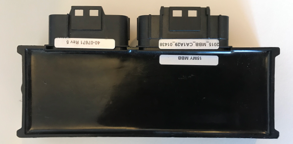 2016 Zero MBB Front
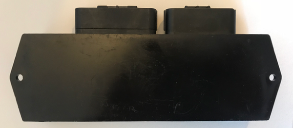 2016 Zero MBB Back
The Main Bike Board (MBB) controls the overall system, implements safety interlocks, and directs the controller.
It is also the entry point for configuring these systems, performing diagnostics, and examining operational events.
When referring to "the firmware", or "the logs", people are referring to this board primarily, and possibly the BMS.
It is enclosed within a fully-potted plastic-like container with multi-pin connectors along the top side.
Location (S Platform)
Below the front area of the seat under cable runs.
It is located aft of (and above) the DC-DC 12V Converter with a bracket sandwiched between them.
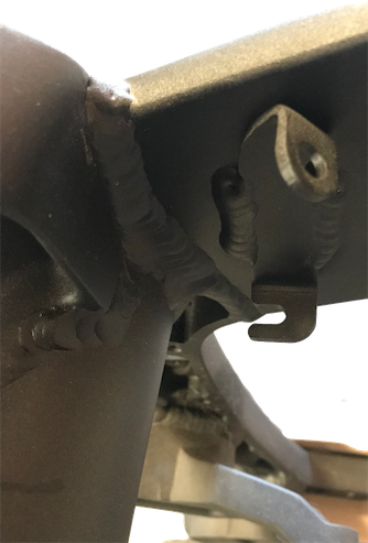 Board Plate Mounting Bracket (Left)
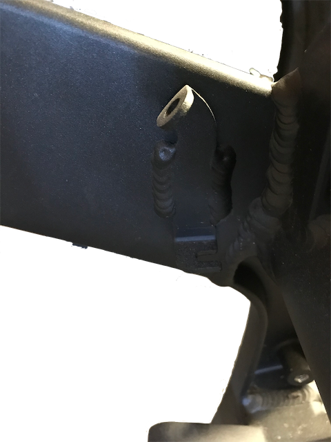 Board Plate Mounting Bracket (Right)
Location (X Platform)
Below the front modular battery (or front half of a longbrick battery) in the triangular bay above the controller.
Mounting (S Platform)
Two socket head bolts with washers fasten the enclosure to a vertical plate.
The bolts enter the plate in the forward direction but offer very limited clearance for manipulating them.
NOTE: on the right, the cables from the controller to the motor run past.
A very small angled 3mm Allen Key wrench is best for unmounting the board.
When using the OBD2 port, the board's application firmware supplies the interactive console.
Playing with the 2012 MBB shows Doctorbass' transcript using 2012 firmware.
- 2013 models' interface differs quite a bit from this but the general logic and experience are the same.
Protections
The board appears to be permanently sealed and potted within the enclosure to protect it from dust and a certain amount of moisture ingress.
Interlock Troubleshooting
Use careful electrical isolation measures when troubleshooting electrical switches used as inputs for interlocks enforced by the firmware.
Replacement
The board must have its firmware setup specific to the bike in question.
Major firmware difference exist across model years such that the firmware binary in question must be selected to prevent major problems on replacement.
- NOTE: Apparently only the manufacturer can perform this provisioning (probably imaging the base kernel, userland, and application-container management).
A dealer must select the correct and latest applicable application firmware to apply to the bike per its basic parameters:
- Year
- Model
- Battery configuration
Information from the bike's VIN is necessary to select the right programming by the dealer or manufacturer.
This information may not be sufficient, if it requires coding in the presence of a Power Tank or Charge Tank.
The board settings require model information to be set per above, and the BMS must agree about this information.
Main Bike Board Limitations
The board design is very modest and seems to prioritize light weight and simplicity over robustness.
Take as much care as possible when troubleshooting in and around this module.
A professional-grade application of dielectric grease around the connectors seems advisable.
- NOTE: Ensure that the entire connector and pins are clean and dry before applying.
Performance and Lockup
The board communicates with the bike's other systems via CAN Bus, which is a 2-wire Multi-master bus.
- This means that multiple nodes on the bus must initiate a transfer.
The board also has limited memory, I/O dispatching, and computational performance.
- So, it can get clogged with requests for data outside its designed parameters.
- So, running any telemetry while in drive mode through the OBD-II serial console or using the Bluetooth transmitter will meaningfully increase the load on the board.
In some cases prevent it from acting on rider inputs, including safety interlocks like the cutout switch or kickstand interlocks.
Reportedly, 2017 and newer models have increased performance and doubled memory capacity.
- This enables an onboard upgrade with an atomic swap of versions by holding new and old firmware versions simultaneously.
- There's no known means of using these in older models.
Electrical Vulnerability
The circuits connected to the pins seem to lack significant protection against shorting faults, which could be a source of breakages while dealing with connected systems.
OBD-II Serial Output
The use of the non-standard OBD-II port most easily draws power from a very limited internal circuit.
The OBD-II port as a result is typically not usable over a long cable without an external power supply and good quality connections.
Main Bike Board Connections
The board has a 34-pin and 40-pin connector exposed through the top of the enclosure, making them relatively accessible and a way to identify the component.
Both are made by JAE Electronics.
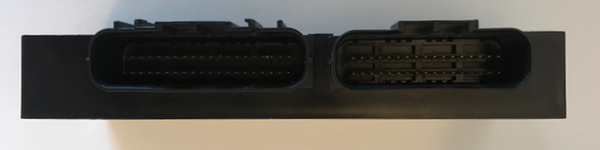 2016 Zero MBB Top
| Connector | Harness-side | MBB-side | Notes |
|---|---|---|---|
| 34-pin connector "MBB 1" | JAE Electronics MX23A34SF1 | JAE Electronics MX34A34NF1. | 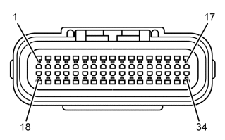 Harness-side pinout; MBB side mirrored 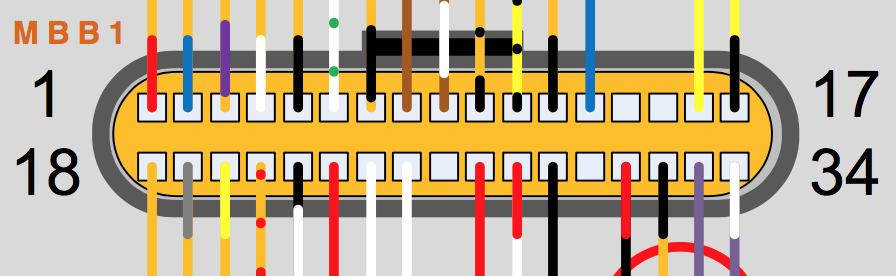 2013 MBB 1 connector Wiring Diagram image |
| 40-pin connector "MBB 2" | JAE Electronics MX23A40SF1 | JAE Electronics MX34A40NF1 | 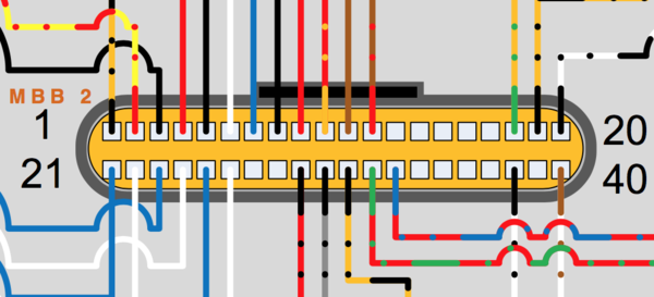 2013 MBB 2 connector Wiring Diagram image |
| Component | Function | Wire | MBB Pin | Role |
|---|---|---|---|---|
| Kickstand Switch | Safety Interlock | Red (2013) 20AWG | 27 | Colors are different for 2016 models: |
| 〃 | 〃 | Orange (2013) (black) 20AWG | 12 | Blue (5v power), Pinkish Red (measure signal TODO), Black. Do not short these directly. That is not how you bypass. |
| 〃 | 〃 | Yellow (2013) (black) 20AWG | 11 | Kickstand Switch |
| Kill Switch | Safety Interlock | Red 20AWG | 23 | |
| 〃 | 〃 | White 20AWG | 24 |
| Component | Function | Wire | MBB Pin | Function | Notes |
|---|---|---|---|---|---|
| DC-DC Converter | Enable Signal | Orange (Red) 18AWG | 21 (2013) 20 (2015) |
DC-DC 12V converter
The DC-DC 12V converter is a solid state switching power DC step-down converter designed to produce low voltage DC power from the pack voltage.
The converters mentioned here are used on Gen2 and Gen3 models.
| Years | Platform | Manufacturer | Model | Replacement Options |
|---|---|---|---|---|
| 2013-2014 | S and X | Sevcon | Sevcon DC-DC 300W converter | OEM or via Thunderstruck Motors - NOTE: Select the 300W model! connector hardware is an extra |
| 2015+ | 〃 | 〃 | Sevcon DC-DC 500W converter | OEM or via Thunderstruck Motors - NOTE: Select the 500W model! connector hardware is an extra |
Appearance
It's about the size of a long box of soap with a black surface, but for 2013-2014 models will be covered entirely with Nashua aluminum ducting tape, so will appear silver.
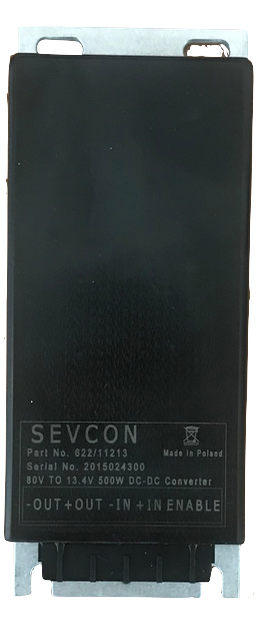 500W Sevcon DC-DC converter - top |
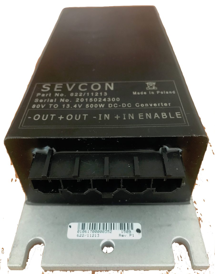 500W Sevcon DC-DC converter - connector 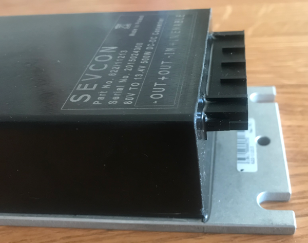 500W Sevcon DC-DC converter - connector side |
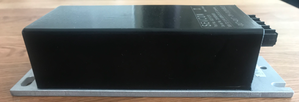 500W Sevcon DC-DC converter - side 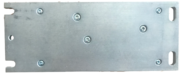 500W Sevcon DC-DC converter - backplate (upside down) 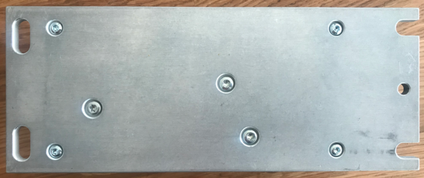 500W Sevcon DC-DC converter - backplate (as installed) |
SDS Platform Location
Below the front of the seat under cable runs, between the MBB (separated by a bracket) and the back of the battery frame area.
Quick and dirty illustrative video of how to find and access the converter
XMX Platform Location
Below the removable battery compartment. See our FX teardown layout guide.
FST Platform Location
Inside the tank, on the right of the bin, on the board mounting plate.
Protections
- Ingress: IP67
- Short circuit overload
- Reverse polarity
- Fully isolated
- Can parallel with diode safeguard
Mounting
The Sevcon 500W DC-DC converter is mounted to its own baseplate via 4 Torx T10 cap head screws and there are 3 additional Torx T15 cap head screws in the middle.
The Sevcon baseplate is then bolted to Zero's board mounting plate with 4 10mm hex head bolts which have 6mm outer diameter, 16mm length, and 1mm pitch.
Removal
- Remove the board mounting plate.
- Remove the converter from the board using a 10mm hex socket wrench.
- Disconnect the connector if appropriate.
Installation
- Attach the converter to the board mounting plate with a 10mm hex socket wrench.
- Install the board mounting plate with the converter back into the bike.
Connections
There is a 5-pin connector controlling the converter, facing the left as installed on the bike, connected as follows:
| Pin | Function | Measurement | Component | Years | Wire | MBB Pin | Illustration |
|---|---|---|---|---|---|---|---|
| 1 | Enable signal | Battery voltage when key is on | MBB | 2013 | Orange (Red) 18AWG | 21 | 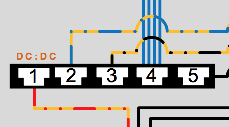 |
| 〃 | 〃 | 〃 | 〃 | 2015 | 〃 | 20 | 〃 |
| 2 | Input (Positive) | 116V | Battery | 2013 | Orange (Blue) 16AWG | 7 | 〃 |
| 3 | Input (Negative) | 〃 | 〃 | 2013 | Orange (Black) 20AWG | 5 | 〃 |
| 4 | Output (Positive) | 13.5V | Fuse Block | 2013 | Blue (16AWG, 14AWG) wires | 〃 | |
| 5 | Output (Negative/Ground) | 〃 | 12V return conduits | 2013 | Black 10AWG | 〃 |
Output
It is configured to output 13.5V DC; usually produces ~13.8V DC.
There is very little ripple that is typical of a gas-power motorcycle's alternator-driven DC supply.
Capacity is 300W (20-25A) for pre-2015 bikes and 500W (35-40A) for 2015+ models, with most of that excess needed to run ABS pumps, etc.
Operation
The input side is always-on DC from the battery, upstream of the contactor.
This is the best place to tap for an always-on power supply.
The converter is enabled by a 12V signal from the MBB.
Environmental Vulnerability
- The Sevcon DC-DC converter is rated to IP67 for intrusion protection and seems very robust as such.
- However, the connector is not sealed, faces the left side of the inside of the frame arms with not much splash protection from beneath; on 2015+ models, it is also vulnerable to debris and splash impact from the rear near the motor and belt.
- No sealed connector option is currently available for Sevcon's DC-DC converter models that Zero uses.
- Connector looseness could age and wear the converter prematurely due to sporadic voltage input or output changes.
- Leakage across pins could cause the enable signal to activate inadvertently.
Connector Inspection
Try to inspect the pins' tabs to ensure they are in the right shape to clamp that enable pin securely.
The connector is not well-sealed, and the pins are too easy to bend into not-connecting if there's any tension/tugging on the wires.
If the connector seems grimy, remove and clean it while de-energized; then apply grease once dry before re-seating it.
Test the connector before fully re-assembling the bike.
Failure to De-energize Condition
The converter can fail in a way where it shorts its enable line and will not turn off even if the bike is keyed off.
- If this condition happens in rain:
- Let the bike dry out until it clears.
- Attempt a dielectric grease application to the inputs while de-energized.
If the DC system output disappears:
- Check DC voltage upstream of the fuse block in case the fuse block is faulty.
- Check the continuity and snugness of the connectors and pins.
- Check for the enable signal from the MBB
Continuity: < 1Ω between pins.
Not shorted to B+?: > 151kΩ from pin 20 to pin 7.
Not shorted to ground?: > 1MΩ from pin 20 to 18.
Protection Recommendations
- Splash protection around the left-side's connector from all sides is worth considering.
References
Re: My DC-DC converter has died again, local dealer has gone bust
Re: A puddle, some rain and some problems
Power Harness
The power cables and signal wiring that connects the MBB to the BMS units intended for that platform and year are collectively bundled and referred to as a “power harness”.
Loopback Blanking Plug
The loopback blanking plug is a Zero electrical connector cap that wires two pins together in a loopback circuit.
This meant to emulate a basic connectivity feature for the BMS1 connection so that the vehicle's CAN Bus can operate properly.
If you own a non-longbrick X platform model or an S-platform model with a Power Tank, retain this blanking plug in case your second BMS fails to connect or issues errors that prevent your motorcycle from operating.
Loopback
BMS CANBus loopback is a function of the built-in cable communications support for the Power Tank or the second Power Pack Module in a non-longbrick X platform model (labeled BMS1 by the MBB).
The cabling ends in a multi-pin connector and should either:
- Terminate with a Loopback Blanking Plug that wires two pins together in a loopback circuit.
- Connect to a Power Tank's corresponding communications cable.
If one of the above conditions do not hold, the MBB is configured to issue error code 35.
It is unconfirmed what purpose the loopback mechanism serves.
Hypothesis: This is a hardware debugging mechanism for a loose connector.
Firmware Update
Firmware update refers to the process of acquiring and installing newer firmware versions from Zero onto the MBB, BMS, and the motor controller.
Dealership Updates
Firmware update for pre-2017 models must be performed by a dealership with a license with Zero and the hardware kit to connect a Windows computer to the motorcycle's data ports (OBD-II, the BMS serial port, and the Sevcon 34-pin connector).
Mobile App Self-Service Updates
On 2017 and newer Zeros, it's possible for the user to upgrade the firmware via the Zero Motorcycles mobile app.
Firmware Versions
Using the Zero App to download the logs, and Phreak's Log Parser Utility (forum, Github, online), different users have reported the latest firmware versions to be:
| MBB | BMS | |||
|---|---|---|---|---|
| Board Year | Revision | Version | Revision | Version |
| 2013 | 1 | 67 | ||
| 2014 | 1 | 44 | 1 | 43 |
| 2015 | 3 | 25 | ||
| 2016 | 3 | 51 | 3 | 39 |
| 2017 | 12 | 21 |
The online log parser has a list of the most recent firmwares that have been uploaded to the server: Latest Firmware Versions
Feel free to update this section as you discover new available updates.
| Version Changes | |||
|---|---|---|---|
| Component | Version | Release Date | Notes |
| BMS | |||
| MBB | 48 | spring 2017 | |
| 〃 | 49-51 | 49 Build Date: 06Jul2016 51 Build Date: 25Apr2017 |
Confirmed: SoC improvements, particularly for pre-2016 model years. Observed: 2016 SoC is significantly more pessimistic in v51 than in v49. Guess: Throttle remapping to a smoother roll-on curve. Guess: Regen seems to apply more broadly. |
Problems
- Firmware mismatch problems (bms on power tank versus ZF pack)
- SoC problems
- Which versions are known safe?
- Observed changes
- Differences by year/model
- MBB
- BMS0
- BMS1
Upgrading Firmware
As of 2017, Zero models are capable of performing remote firmware updates by the customer using the mobile app.
Apparently this doesn't transfer to older models because the older boards did not have enough storage space to perform an atomic/reversible update.
This means holding both firmware versions and being able to toggle which version to use.
So, if anything goes wrong with a firmware update, the system can roll back to the previous version without requiring a dealer visit.
ChangeLog
Zero Motorcycles on their website now lists changes of Zero Motorcycles vehicle firmware
Source: zeromanual.com/wiki/FST_Platform/Unofficial_Service_Manual · Wayback capture of 2025-05-17 · wiki last edited 2 May 2020 00:04. Community-written content from the Unofficial Zero Manual, reproduced for preservation; not written or verified by OpenZero. Links to pages that were not mirrored go to the Wayback Machine.