Final Drive
Swingarm
The swingarm is a dual-sided structure made in the same way as the frame. It's very sturdily constructed for its light weight.
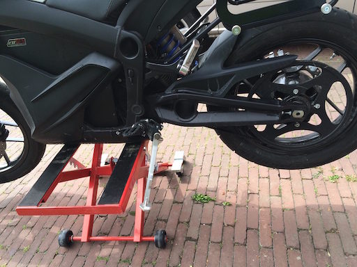 Swingarm
The front pivots on the axis of the motor to minimize belt strain with suspension travel.
It has fitments for the rear axle including belt tension adjustment.
Mounting
The swingarm joins the frame at left and right pivot points.
The each side pivot has a stack of (from outside inward):
- A rubber cover
- A bolt with a 10mm hex drive.
- The bearing (6204; 6204RS for 2015+ models)
Swingarm Tube
There is a hollow tube through the swingarm across the arms forming a join point for the rear shock to the frame tube on the SDS platform.
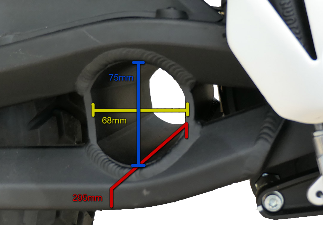 Swingarm Tube with measurements
Its shape is flattened on the rear side, presumably to clear the largest-diameter potential tire.
It makes a reasonable storage tube if some padding or caps are used to secure the cargo there (like a charging cord).
| Inner diameter | 75mm | 2.91" |
| Horizontal width to flat side | 68mm | 2.68" |
| Swingarm greatest width below tube | 295mm | 11.61" |
References
Re: Through-frame security aperture size?
Swingarm Bearings
The swingarm bearings are generally the same as the wheel bearings (6204; 6204RS for 2015+ models).
Swingarm Removal
Tools
- Center lift or other lift that gets the rear wheel off the ground without contacting the swingarm.
- 27mm socket or spanner.
- 3mm Allen key.
- 10mm Allen key socket
Ensure at least 1" depth and a ⅜" drive sufficient to handle swingarm pivot bolt torques. - 15mm socket wrench (S models). - 13mm socket wrench (X models). - Torque wrench capable of setting 75ft-lbs and driving the 27mm socket and 10mm Allen key. - 2012-2013: - 2.5mm Allen key. - 24mm socket wrench.
Steps
NOTE: For roadside removal, particularly for an FX or FXS, setting the bike on its side should be possible for this work.
However, no effective procedure has been described for the process.
The following steps are suited to garage locations.
Bike on center lift
- Use a lift to raise the bike from the center.
A sturdy wood crate may work in a pinch. Be safe.
If the lift can be adjusted, lift the rear wheel just off the ground for ease of removal and replacement (lower than depicted but not in contact). 2. Pull the wheel off (or slide it forward) by loosening the axle nut with a 27mm wrench. 3. Pull off the rear tire fender by taking out the 4 hex bolts securing it with a 3mm Allen wrench.
You can get away with removing only the left-side screws, to allow lifting the fender up enough to get the belt under.
The right side fasteners also anchor the brake line to the rear calipers and a grounding strap, so mind them for re-attaching in the same way. 4. Remove the brake pedal:
This creates clearance for loosening the swingarm bolt above it (might be optional for pre-2015 models). 5. Get the rear brake pedal out of the way of the right side swingarm pivot bolt.
SDS platform: Use the 15mm hex socket to loosen or remove the bolt forming the pedal pivot.
XMX platform: 1. Remove the pin that attaches the brake pedal to the piston. 2. Remove the two 13mm bolts that hold the grey piston bracket to the frame, and gently move the whole assembly to the left.
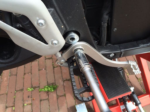 Rear Brake Lever Bolt
6. XMX platform: To access the left swingarm bolt, remove the lower left passenger peg bolt (13mm) and remove the grey cover piece.
7. Remove the left and right swingarm bolts.
2012-2013
Remove the set screws from the swingarm bolts on both sides with a 2.5mm Allen wrench.
The set screw is very difficult to find.
It is located in one of the sides of the 24mm hex nut, perpendicular to the long axis of the 10mm allen bolts.
It is actually on the edge of the nut.
The best way to locate it is to use a small mirror and a strong flashlight.
Then remove the bolts by holding the inside nut with a 24mm wrench, and a 10mm hex on the head.
This was the hardest step, because there is not a lot of room to manipulate in the rear assembly - especially with a 24mm wrench!
2014+
Remove the left and right swing arm bolts with a 10mm Allen wrench.
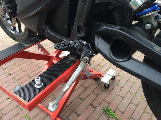 Swingarm Bolt
8. Hang the swing arm with a strap on the tail section.
The swingarm will pull back enough for the belt to fit through the frame.
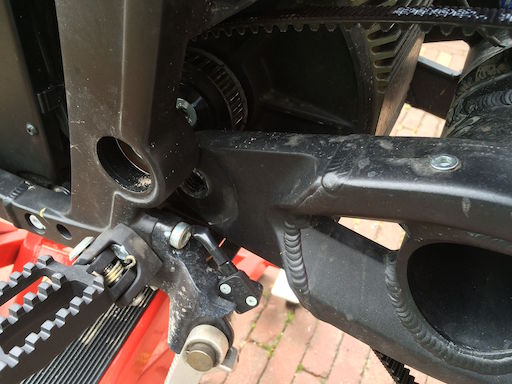 Pulling the Swingarm
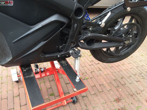 Swingarm Pulled
9. Remove the belt.
10. Disconnect the rear shock from the swingarm, then gently pull the swingarm from its suspended arrangement. Take car that the small spacers do not fall out and roll away, one on each side.
References
Rear Axle
The rear axle is hollow, threaded on the right side and capped on the left for swingarm fitment.
| Years | Inner Diameter | Outer Diameter | Pitch |
|---|---|---|---|
| 2013-2014 | |||
| 2015+ | 11mm | 20mm | 1.25mm |
Removal
This removes the Rear Axle part of Rear Wheel Removal.
Tools
- 27mm socket
- Breaker bar
Instructions
- Place the motorcycle on a lift or rear stand
Raise just enough that the rear wheel spins freely. 2. Mark/photograph where the alignment marks reside on each side of the axle for re-alignment when re-installing the wheel. 3. On the right side, loosen the rear axle nut (27mm) with the breaker bar. 4. Remove the rear axle nut. 5. Pull the axle part-way out so that the wheel can be moved forward enough to loosen the belt. 6. Pull the belt off of the rear sprocket.
Let it hang outside of the swingarm slightly to avoid interfering with the wheel. 7. From the left side, pull the axle through the wheel.
Install
To replace the rear axle, see rear wheel replacement.
Belt
Zero uses a belt for primary transmission of torque to the rear wheel. It's quiet and lightweight but is a proprietary design that can wear out. If you plan to put a lot of miles on a Zero or risk the belt often, buy a spare belt ahead of time and mind its maintenance.
Belt Risks
Drive belts fail by snapping or by stripping the teeth.
On Landing
The most common situation for a belt snap is when going over a major bump or jump where the rear wheel leaves the ground.
- If, while airborne, the throttle is not immediately relaxed, the rear wheel will rapidly spin up.
- A wheel that is moving extremely quickly in the air will get jerked back to its regular speed on landing. This is transmitted to the belt through the rear sprocket and can easily strip teeth.
From Debris
Gravel or sand that gets thrown between sprocket teeth and the belt will force the belt to expand quickly under load, and can cause it to snap.
Reportedly, sand is a much more reliable path to belt failure than gravel.
The sprocket tooth design is meant to deflect gravel to the inside of the swingarm towards the wheel.
The bike has an upper debris guard made of soft ABS plastic, but does not have a lower guard.
From Mis-Alignment
An unaligned belt can wear really badly and break sooner.
Belt Specifications
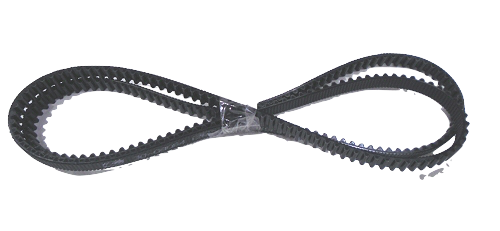
Zero's final drive is a custom-designed Gates HTD (high torque drive) Poly Chain Carbon toothed carbon fiber belt.
- It's never been available outside of Zero's parts system.
- It's been the same part for 2012-2016 models.
2017 models shifted to a wider belt that can accommodate more torque/loading.
| Years | Width | Pitch | Models | Sprockets | Number of Teeth | Length | OEM Part No. | Photo |
|---|---|---|---|---|---|---|---|---|
| 2010-2011 | 14mm | 8mm | S/DS | 98T / 28T | 200 | 30-02641 | ||
| 2012-2016 | 〃 | 〃 | S/SR | 132T / 28T | 220 | 30-03673 (old logo) 30-08084 (new logo) |
 |
|
| 〃 | 〃 | 〃 | DS/DSR | 130T / 28T | 〃 | 〃 | 〃 | 〃 |
| 2017- | 17mm | 14mm | S 13.0 | 130T / 28T | 〃 | 〃 | 〃 | 〃 |
| 〃 | 〃 | 〃 | FX/FXS DS/DSR SR/S6.5 |
90T / 20T | 158 | 30-08086 | 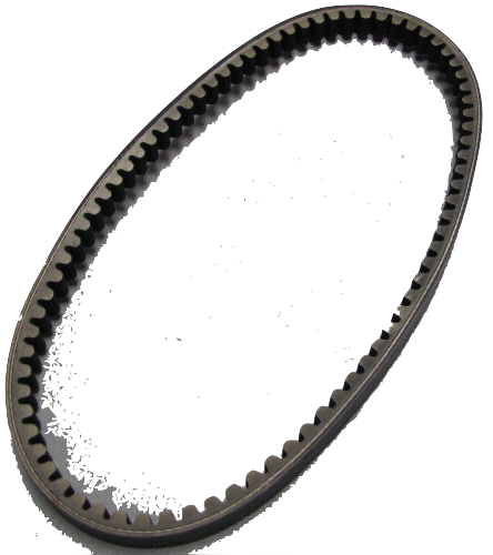 |
|
| 2020- | 20 | 11 | SRF | 90T / 20T | 151 | 30-08226 |
Part
Gates GT Carbon, 14mm wide, 8mm pitch, 220 teeth. It's only available from Zero.
P/N's are 30-03673 ("Belt Drive, 220T, 8mm Pitch, 14mm Wide") and also 30-08084 (same belt w/new Zero logo).
One rough match for reference: Gates 8MGT-1760-12 Belt
Another Gates product page that highly indicates a product/technology match: Poly Chain® GT® Carbon™ synchronous belts per Gates drive belts (EMF Thread)
Belt Tension Check
Krikit Tension Gauge
Zero recommends the Gates Krikit belt tension gauge to check belt tension.
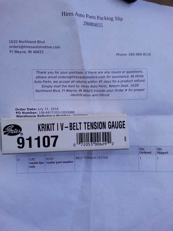 Krikit Tension Gauge invoice and box
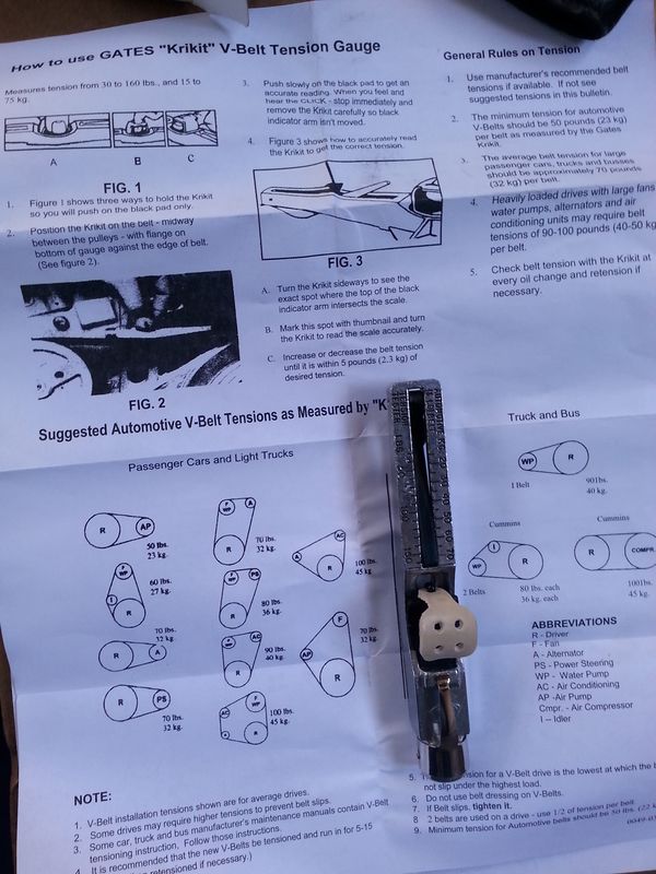 Krikit Tension Gauge gauge and instructions
Video Guide
MostlyBonkers made a How-to video:
Tips
- Turning the back wheel backwards before measuring will give different readout compared to turning the wheel forwards before measuring using the same spot.
The difference may be significant to the (pre-2017) 20-30kg belt tension specification.
For wide-belt 2017+ models, the tension specification is very wide (~25-75kg) and thus has a lot of leeway but seems worth a rotational check anyway. - The center of the belt can be reached from below, without removing the mudguard.
This is described as a note in 5.14 in the 2015 manual
Steps
More detailed generic instructions for the Krikit deflection device
- Ensure the blue indicator arm is pressed down.
- Place the gauge in the center of the belt span, such that it is aligned longitudinally with the belt length.
- Place a finger on the blue pressure pad and depress this pressure pad.
- Keep pressing the blue pressure pad until you feel and hear a distinct 'click'. When this 'click' sound is heard, do not press any further.
-
Remove the gauge and read the belt tension by observing the point where the top side of the blue indicator arm crosses the numbered scale on the gauge body.
-
Care must be taken to ensure that the gauge is not 'rocked' when pressing down on the blue pressure pad. The strap above the pressure bar is provided to attach snugly over the finger and prevent any 'rocking' motion.
- Due to the fact that this device requires some amount of practice and operator skill, the accuracy and repeatability of the tension readings are not high.
Improvement
Because this procedure is not trivial to perform consistently, there is a modification to make the tension gauge easier to align
Gates' Carbon Drive mobile app
As of 2017, the Official Owners Manual also includes a procedure using Gates' Carbon Drive mobile app to check belt tension.
Usage
- Use the application in a quiet environment.
- Pluck the belt near the center of the lower belt span, so it vibrates like a guitar string.
| Belt Type | Years | Resonant Frequency | Tension Range |
|---|---|---|---|
| Narrow | 2013-2016 | 96.3 Hz – 124 Hz | 20 – 30kg |
| Wide | 2017+ (except S 13.0) | 42.5 Hz – 73.6 Hz | 25 – 76.5kg |
The frequency can also be checked with instrument tuning apps such as Tuner-gStrings for Android.
Belt Adjustment
Goal
Align and set belt tension to avoid bad wear and early breakage.
Alignment of the belt is critically tough to get correct, and needs to be done everytime adjusting tension.
Zero's Official Owners Manual has a good procedure from which this is derived. Check that first.
Video instruction
Zero SR: How To Adjust Your Belt on Youtube by NewZeroLand:
Tools
27mm hex socket
Breaker bar
Torque wrench set to 75ft/lbs or 102Nm
13mm open-end wrench
Instructions
- Place the motorcycle on a Lift or rear stand so the wheel spins freely.
- Loosen the rear axle nut on the right side (27mm) with the breaker bar.
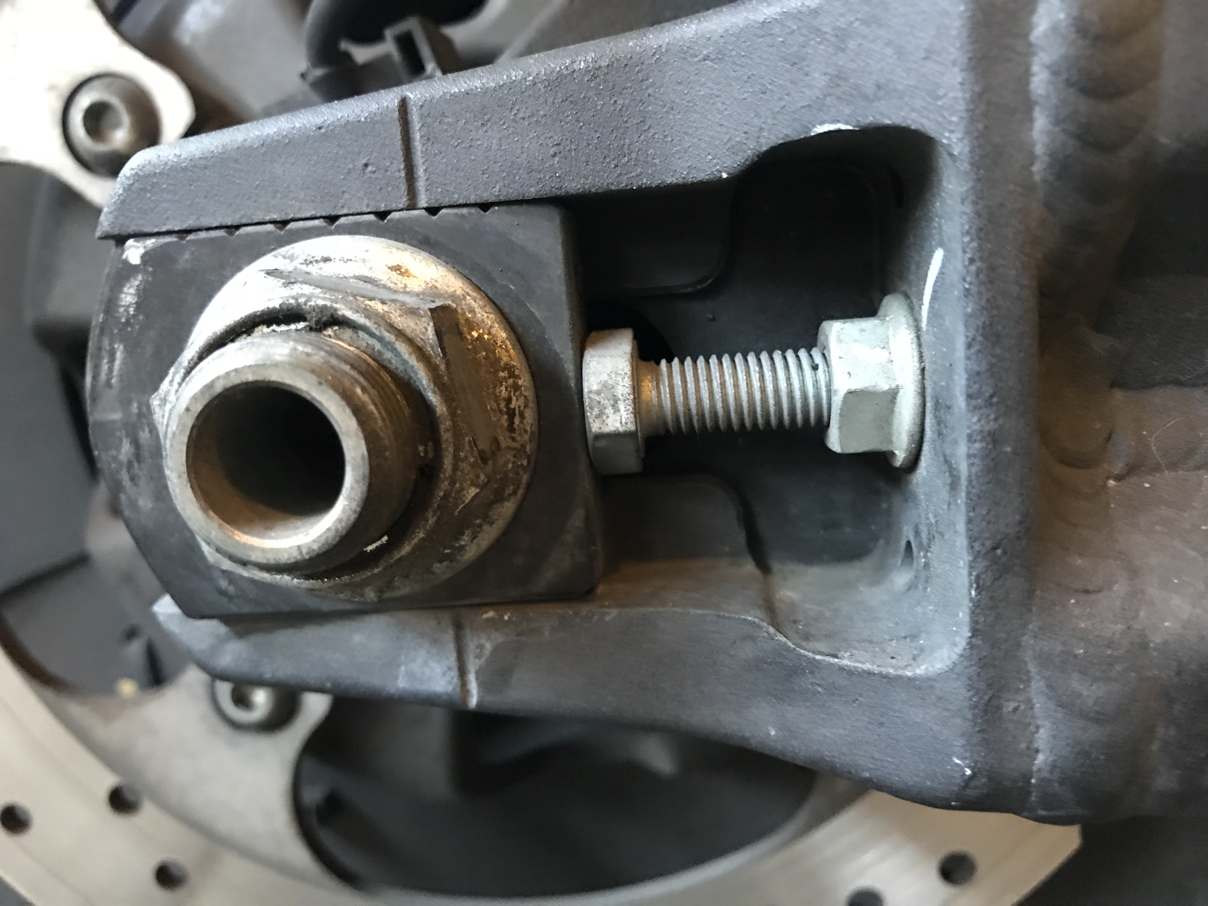
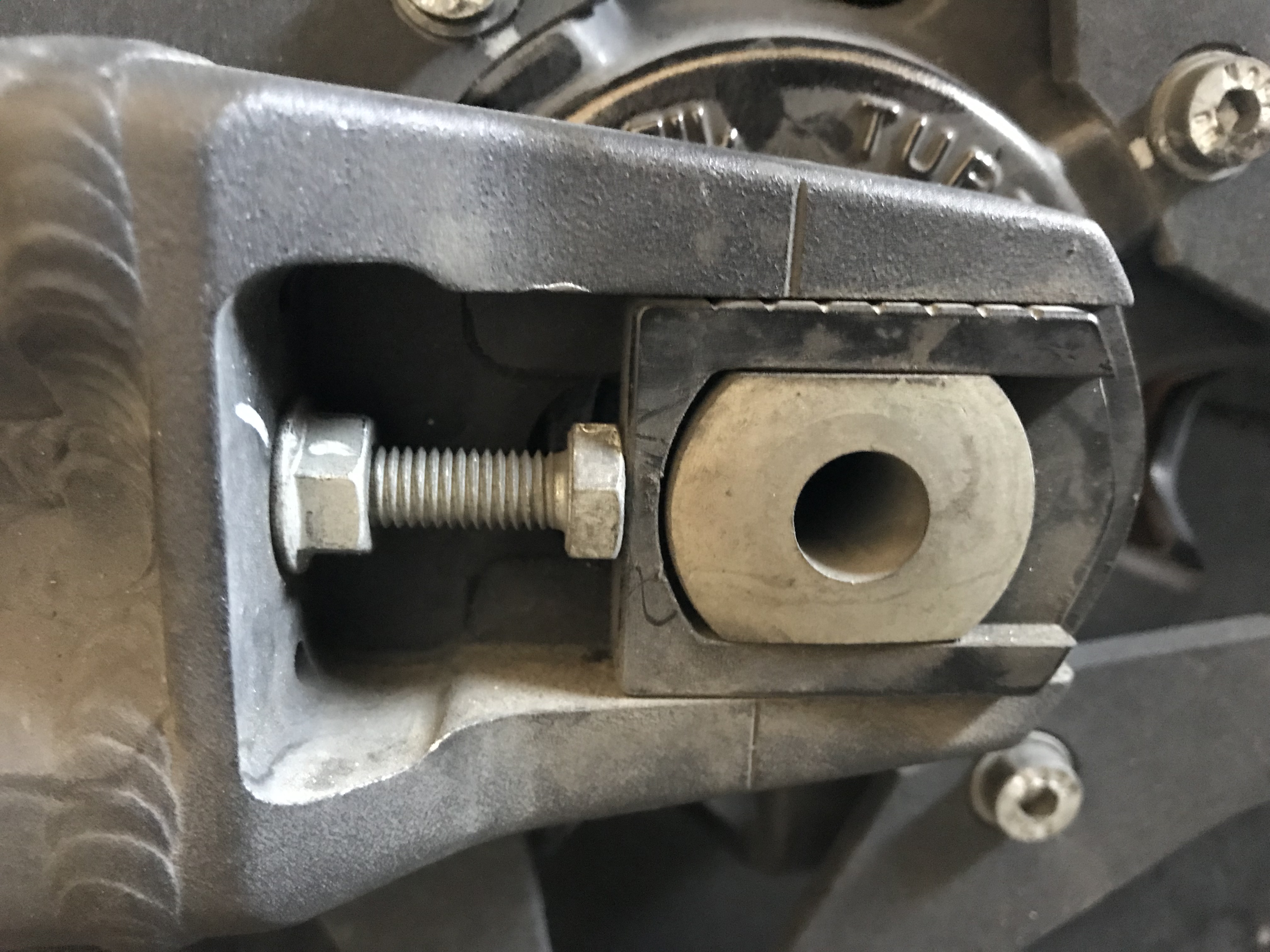 3. Loosen both left and right belt tension jam nuts (13mm) that face forward inside the adjusting gap.
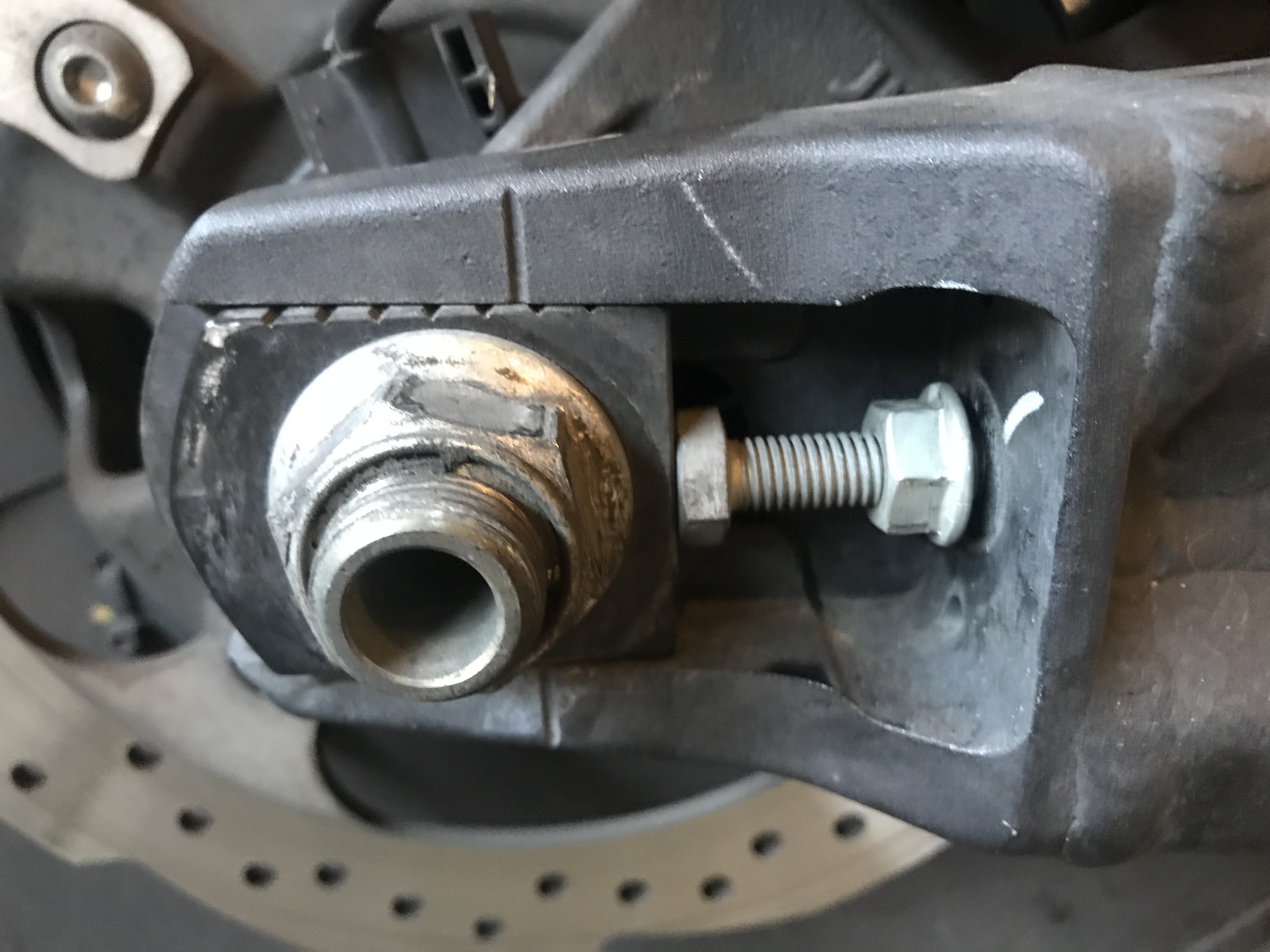
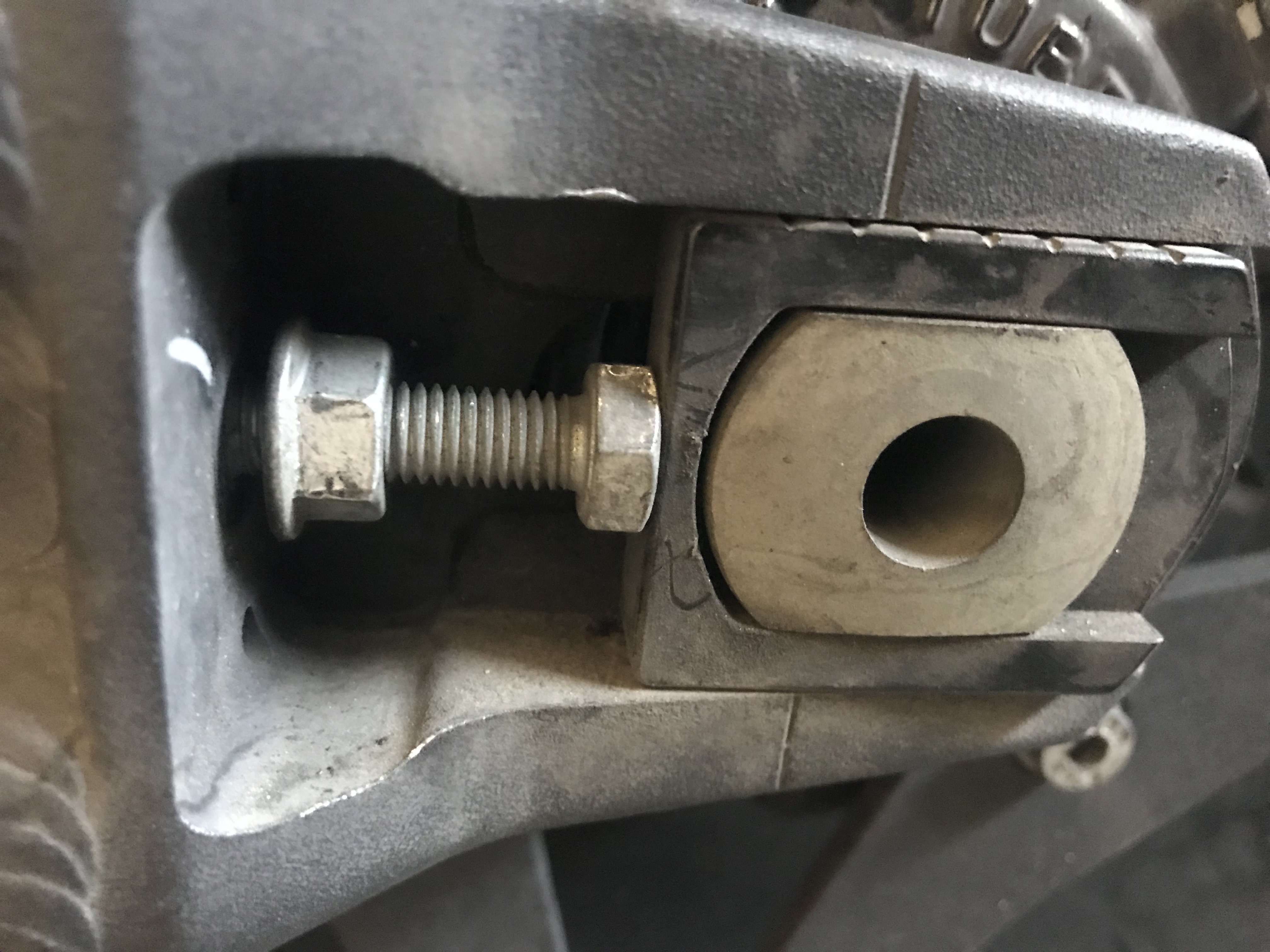 4. Turn both left and right adjustment nuts (13mm) one quarter turn at a time to the desired belt tension.
- Ensure that the alignment marks on either side of the swingarm indicate that the wheel and belt are aligned.
- Roll the wheel forward and track it flush with inside of rear sprocket.
- For proper alignment, the belt will track exactly centered on the wheel sprocket with a 1mm gap to either side of the belt relative to the sprocket.
Once tension is set and tracking is flush to the inside, tightening the axle nut to 75ft-lbs will tend to nudge belt approximately 1mm to the outside.
-
Measure tension by rolling the wheel forward while plucking bottom side of belt or using tension gauge over several revolutions.
Expect tension to vary slightly as wheel is rotated because front and rear sprockets are only round to a certain design tolerance. 5. Check that the belt is aligned with belt tension in the right range. 6. Re-tighten the left and right jam nuts (13mm). 7. Tighten the axle nut (27mm) with the torque wrench (to 75ft-lbs).
References
How to Adjust Your Zero's Belt
Belt Wear
Generally, watch for belt damage and try to anticipate when to replace the belt to avoid an incident on the road where the belt snaps.
What to Check
- Check the teeth for wear and cracks.
If you see cracks in the tooth forming, the belt is getting old.
If you see deep cracks starting, it's time to replace the belt ASAP.
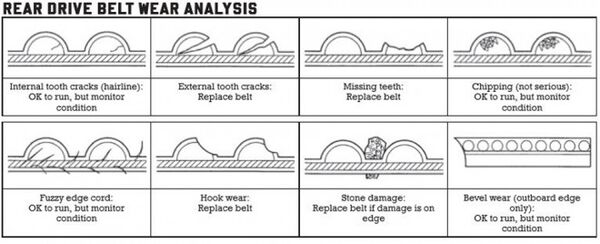 Rear Drive Belt Wear Analysis
When to Replace
- When it snaps.
- When any teeth have been ground off.
Hard Skips
- If the belt experiences a "hard skip" from debris between the belt and a sprocket, it is likely to fail soon after. Watch it carefully if this happens.
Tension with aging
Apparently, per forum user JaimeC, belts don't wear like chains.
As they get older they'll actually get tighter, not looser like a chain.
- When a chain ages, the little bearing points between the links and rollers wear causing the chain to hang looser.
- When a belt ages, the rubber on the inner/toothed side begins to swell.
Since the Kevlar belt on the outer circumference won't stretch, the inner circumference will shrink making the belt tighter around the sprockets.
Generally, you want to make sure the belt hasn't gotten any tighter since you brought it home.
References
Belt Replacement
Ask your dealer/Zero before replacing it.
They may perform it under warrantee if it happened prematurely; and they'll likely want to understand how and why it broke, anyway, for quality reasons.
Video Guides
- How To: Replace Your Zero Motorcycle Belt by NewZeroLand on YouTube:
- Zero emergency toothed belt by UW4E on YouTube:
Tools
- Center lift.
- 27mm socket.
- 3mm Allen key.
- 10mm Allen key socket
Ensure at least 1" depth and a ⅜" drive sufficient to handle swingarm pivot bolt torques. - 15mm socket wrench (S models). - 13mm socket wrench (X models). - Torque wrench capable of setting 75ft-lbs and driving the 27mm socket and 10mm Allen key. - 2012-2013: - 2.5mm Allen key. - 24mm socket wrench.
Procedure
NOTE: For roadside belt swaps, particularly for an FX or FXS, setting the bike on its side should be possible for this work.
However, no effective procedure has been described for the process.
The following steps are suited to garage locations.
Bike on center lift
- Use a Lift to raise the bike from the center.
A sturdy wood crate may work in a pinch. Be safe.
If the lift can be adjusted, lift the rear wheel just off the ground for ease of removal and replacement (lower than depicted but not in contact). 2. Pull the wheel off (or slide it forward) by loosening the axle nut with a 27mm wrench. 3. Pull off the rear tire fender by taking out the 4 hex bolts securing it with a 3mm Allen wrench.
You can get away with removing only the left-side screws, to allow lifting the fender up enough to get the belt under.
The right side fasteners also anchor the brake line to the rear calipers and a grounding strap, so mind them for re-attaching in the same way. 4. Remove the brake pedal:
This creates clearance for loosening the swingarm bolt above it (might be optional for pre-2015 models). 5. Get the rear brake pedal out of the way of the right side swingarm pivot bolt.
S platform: Use the 15mm hex socket to loosen or remove the bolt forming the pedal pivot.
X platform: 1. Remove the pin that attaches the brake pedal to the piston. 2. Remove the two 13mm bolts that hold the grey piston bracket to the frame, and gently move the whole assembly to the left.
Rear Brake Lever Bolt
6. X platform: To access the left swingarm bolt, remove the lower left passenger peg bolt (13mm) and remove the grey cover piece.
7. Remove the left and right swingarm bolts.
2012-2013
Remove the set screws from the swingarm bolts on both sides with a 2.5mm Allen wrench.
The set screw is very difficult to find.
It is located in one of the sides of the 24mm hex nut, perpendicular to the long axis of the 10mm allen bolts.
It is actually on the edge of the nut.
The best way to locate it is to use a small mirror and a strong flashlight.
Then remove the bolts by holding the inside nut with a 24mm wrench, and a 10mm hex on the head.
This was the hardest step, because there is not a lot of room to manipulate in the rear assembly - especially with a 24mm wrench!
XU-2013
sane as above, but needed a 23mm wrench and a 2mm Allen wrench instead of the 24mm wrench and 2.5mm allen wrench
2014+
Remove the left and right swing arm bolts with a 10mm Allen wrench.
Swingarm Bolt
8. Hang the swing arm with a strap on the tail section.
The swingarm will pull back enough for the belt to fit through the frame.
Pulling the Swingarm
Swingarm Pulled
9. Check the front sprocket for debris, and clean it with a firm but non-abrasive brush.
If the sprocket is damaged somehow or the teeth are too worn to engage the belt, get it replaced to avoid damaging the new belt.
The rear sprocket regularly deserves the same treatment. 10. Slide the belt over the front sprocket. 11. Replace the swingarm bolts. 12. Slide the belt over the rear sprocket. 13. Set/adjust belt tension and alignment accordingly. 14. Install the rear wheel 15. Re-check belt tension and alignment. 16. Re-install the rear brake pedal. 17. Re-install the rear tire fender. 18. Extend the sidestand, then lower the bike carefully from the lift onto the sidestand.
References
2012 DS Belt Replacement, by User:DoctorBass
Facebook comments by Bobby Loo.
Sprocket
Sprocket Specifications
| Belt | Front | Rear | ||||||||||
|---|---|---|---|---|---|---|---|---|---|---|---|---|
| Width | Pitch | Years | Models | Teeth | Depth | Bore | Other | Teeth | Depth | Bore | Other | Ratio |
| 14mm | 8mm | 2012-2016 | SR | 30 | 15mm | 1" | key measurements? | 130 | 15mm | 1" | 4.33:1 | |
| 〃 | 〃 | 〃 | FX/FXS | 25 | 〃 | 〃 | 〃 | 132 | 〃 | 〃 | 〃 | 5.28:1 |
| 〃 | 〃 | 〃 | S/DS/DSR | 28 | 〃 | 〃 | 〃 | 130 | 〃 | 〃 | 〃 | 4.64:1 |
| 〃 | 〃 | 2017-2018 | S 13.0 | 〃 | 〃 | 〃 | 〃 | 〃 | 〃 | 〃 | 〃 | 〃 |
| 17mm | 11mm | 〃 | FX/FXS/DS/DSR/SR/S6.5 | 20 | 17mm | spline measurements? | 90 | 17mm | 4.50:1 | |||
| 〃 | 〃 | 2019 | S/DS/SR/DSR/FX/FXS | 〃 | 〃 | 〃 | 〃 | 〃 | 〃 | 〃 | 〃 | 〃 |
Reference
Re: Big belt Kits for pre-2017 bikes.
Sprocket Wear On Belt
Wear debris from the tire or the road can accumulate on sprocket teeth, putting pressure on the belt which can wear it out faster.
Recommendation
Keep the sprocket teeth clean to minimize wear on the belt.
A non-abrasive brush should be effective.
Front Sprocket Removal / Swap
Removing or replacing the front sprocket on S and X platforms.
Video Guide
Some guidance from Terry in this motor removal thread:
- Basically, if you are doing this to try to get more acceleration by moving from a 28 tooth to a 25 tooth, Harlan recommends trading in the DS on a 2015+ SR or 2016 DSR if you need the off road capabilities. You will get much much more acceleration and not hurt your top end performance.
- On the drive belt side, the upper rear 5mm bolt takes extreme care to remove. It is tapered to locate the motor. There is a very strong chance of stripping the head and have to drill it out. Make sure to have a machine shop close by just in case.
-
On the other hand, removal of the motor may not be necessary.
-
The other 7 bolts, 3 on the sprocket side and 4 on the rear brake side are the only thing simple and straight forward.
You will need a special 3" or longer 6mm allen head socket for sticking in the hole through the frame at the front of the motor.
-
Remove the rear brake pedal and assembly to get the heel guard out of the way of the top right rear motor bolt.
Be careful not to strip these bolts either.
They have Loctite; use a torch.
And make sure your local hardware store has these replacement bolts handy in case you have to drill them out.
The rear brake pedal needs to move anyway to get the right swingarm bolt out. - Also the sprocket bolt itself, as well as removing and installing the new sprocket on the shaft can be very difficult. Some of the best professionals have had trouble.
Loctite has been used on everything and you will need a torch to remove them.
Even so, you will need a strap wrench with an old belt as the strap to hold the sprocket and a high power impact wrench. - Even with all that right, you have a chance of stripping or breaking the bolt. The sprocket is pressed pretty tight. - Be very careful not to permanently damage the motor bearings by prying between the motor itself and the sprocket to try to remove it, and also by tapping with a hammer to try to fit the new one on. You will be tempted to do both, but you need to find another way.
A gear puller would be much better. - There are other things to watch for: - Mark your phase leads and pay special attention to the routing. - Don't over-tighten the motor jack nuts and bolts until you have the swingarm back in place as it can pull the frame together slightly making it impossible to get the swingarm in place. - Make sure you unplug the 8 way motor encoder harness and it doesn't get yanked and pull a wire. - The top shock mounting bolt is a 15 and 17 mm and can be done with ratchet wrenches 1/32 of a turn at a time, or without ratchet wrenches if you are known to have extreme patience. It can take a while. The 2014 is a little easier and is (seems to be a) dual 17mm bolt and nut. - The swingarm bolts are 10mm allen head and can be extremely hard to relocate even when working with someone else, a rubber hammer, and a flashlight. Those who have replaced their own belt before can vouch for this. - Again, I doubt too many on this forum have done this, and those who did I'll bet agree with me that it makes more sense after they did it and perhaps had their bike out of commission to work through the things that didn't go right, and would agree to just upgrade to the SR or DSR first vs trying to change the front sprocket. - Also the 25 tooth sprocket will break belts easier as less teeth are engaged than the 28 tooth, which can make it more likely to sheer teeth in the event of a wheelspin, and it bends the belt at a sharper radius which can possibly fatigue the carbon strands more. The SR actually uses a 30 tooth front sprocket which is even nicer to the belt than the 28 tooth.
Source: zeromanual.com/wiki/SDS_Platform/Unofficial_Service_Manual · Wayback capture of 2025-05-17 · wiki last edited 10 July 2020 00:05. Community-written content from the Unofficial Zero Manual, reproduced for preservation; not written or verified by OpenZero. Links to pages that were not mirrored go to the Wayback Machine.