Frame/Bodywork
Frame
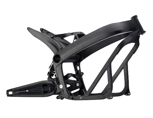 2013 S Platform Frame |
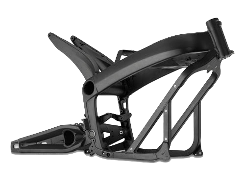 2014-2016 S Platform Frame |
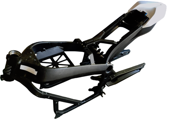 2014S frame isometric |
The 2013+ Zero frame for S/DS/SR/DSR bikes is made of anodized aluminum, weighs 23lbs, and is a combination of cast parts and welded square tubing of 1-inch outer width.
The frame slips onto the battery pack case over the top and attaches to it with four major bolts around the bottom. The charger is attached to the underside with a protective plate covering it (plastic for S/SR, aluminum for DS/DSR).
Attachment Points
The frame offers a number of rivet nut attachment points for the lower plastics.
The rivet nuts are sized to accept M5 bolts (a total depth of 20mm is available without marring the inside of the frame bar) with a 6mm shoulder to a depth of 5mm. (A longer shoulder and length are required for fastening a bracket beyond that.)
From 2015 onwards, the frame has extra attachment points made for the crash bars used for fleet/police models.
Two extra rivet nut holes on each side of the frame diagonal shoulder of the same size. They are 30mm apart (center to center).
The lower bash plate has similar modifications from that year - two rivet nut holes pre-made for M6 bolts and capped by threaded plastic inserts on each side for the lower mount. There is perhaps 10mm thread depth or allowance between the outer surface of the plate and the onboard charger enclosure.
On prior year models, the OEM or dealer would make these fittings.
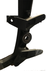
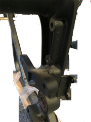
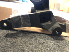
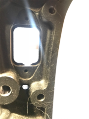
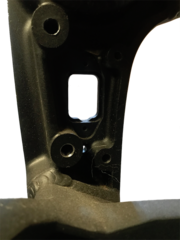
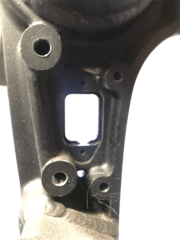
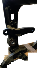
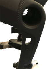
Vertical Stanchions
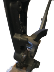
Vertical Stanchion Right
- 
Vertical Stanchion Right
- 
Vertical Stanchion Right
- 
Vertical Stanchion Left
- 
Vertical Stanchion Left
- 
Vertical Stanchion Left
- 
Vertical Stanchion Left
- 
Vertical Stanchion Left
- 
Vertical Stanchion Left
Tail Horns
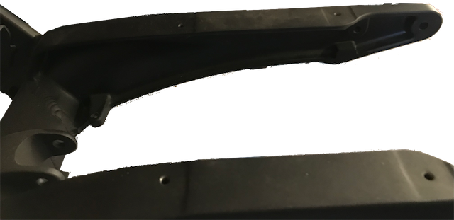
Tail Horns (Left)
- 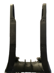
Tail Horns (Top)
- 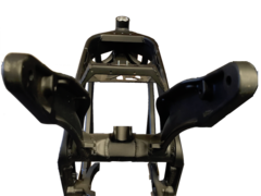
Tail Horns (Rear)
Neck and Shoulder
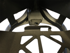
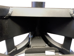
Neck and Shoulder (Top)
- 
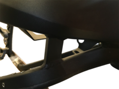
Neck and Shoulder (Rear)
- 
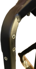
Neck and Shoulder
- 
Neck and Shoulder (Left)
Battery Carrier Tray
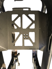
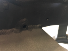
Battery Carrier Tray
- 
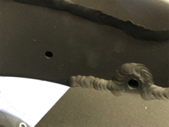
Battery Carrier Tray (Left Holes)
- 
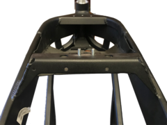
Battery Carrier Tray (Right Holes)
- 
Battery Carrier Tray (Rear)
Board Mounting Plate
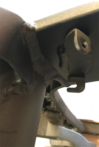
Board Mounting Bracket (Left)
- 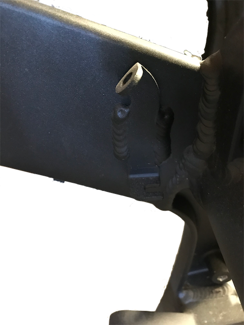
Board Mounting Bracket (Right)
Frame Tube
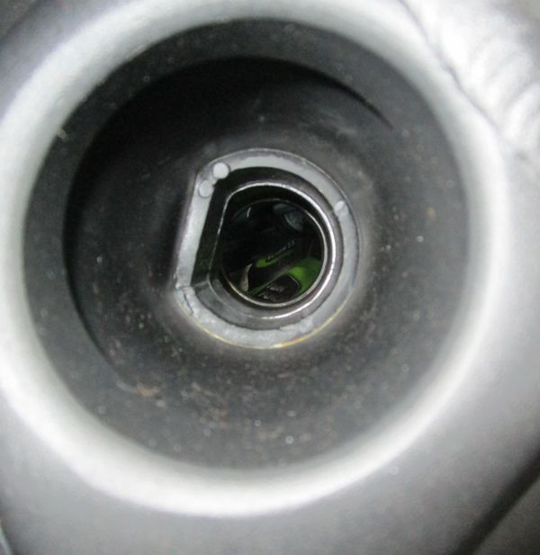 2018 SR Frame Tube Inner view
The frame has a tube running through the center of the bike where the tail horns meet the vertical stanchions and the main forward frame beams.
The tube functions as the anchor and hinge support for the rear shock.
For 2012-2014 models, this inner tube functions effectively as storage for the Charger Power Cord.
2015+ models have a brace in the center of the hole which reduces the diameter in that section.
The rough edges on this brace can abrade the power cord, so for these models, storing the cord there can wear it out over time.
| Inner diameter (2015+) | ~58mm |
| Center Brace minimum diameter (2015+) | ~40mm |
References
Re: Through-frame security aperture size?
Belly Pan
The Belly Pan AKA Skid Plate covers the onboard charger and is metallic on the DS/DSR and a very hard ABS plastic on the S/SR models.
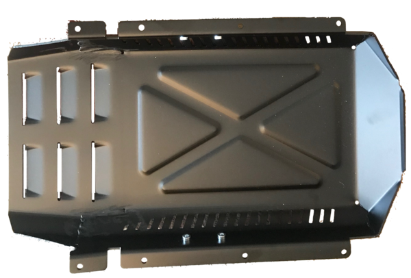 DS Belly Pan / Skid Plate
Both variants are sturdy enough to support the bike on a centerlift.
Parts
S/SR: Hard plastic, part 24-07746.
DS/DSR: Aluminum alloy 5052-H32, part 26-08051 (was 20-05126).
Dimensions
- Lengths
- 20.5in from forward bevel lip to trailing edge below the motor.
- 14.5in along the flat base.
- 2.25in along forward bevel.
- Widths
- 10.25in at the vertical outside face.
- 11 15/16in edge to edge of the flange facing the frame.
- Heights
- 2.5in from frame-facing edge to the bottom edge (not counting louver overhang).
- 1in height 45° bevel.
- Thickness
- 3mm for the DS/DSR metallic pan.
Drop bar Mounts
- 2× holes per side for M6 bolts, 45mm center-to-center forward to aft.
Mounting
Fastened by 8 M5×16-8.8 button head bolts, 4 per side.
Forward corner bolts fasten into corner brackets (part 20-05307) that extend the lower frame square tubing.
Video Guide
How to Remove the Zero's Onboard Charger by NewZeroLand on YouTube from the beginning to 2 minutes in shows very clearly how to remove the pan from a Zero SR.
Tools
- 3mm Allen key.
Steps
- (Optional) Place the bike upright on a front wheel stand if a vertical drop of the pan is suitable.
- Loosen each of the 8 bolts retaining the belly pan (4 per side), without removing.
- Remove each fastener in some suitable rotation so the pan isn't temporarily left dangling by one fastener.
The pan is lightweight and can be manually suspended if convenient, or use a lift to catch the pan and lower it. 4. Set the bolts aside with the pan for replacement later.
Y-Shaped Underseat Frame
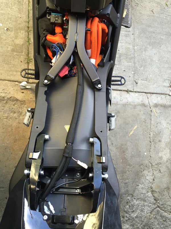 2016 DSR underseat view
This frame piece spans the top of the frame between the part that sits behind the battery doghouse and the tail.
Functions
- Support and anchor the seat by two pins extending from the forward center section.
- Anchor the rear of the tank plastics.
- Mount the 12V Fuse Block on the left rear leg.
- Distributes the seat loading between the forward frame bracket arching over the monolith, and the horns of the rear tail.
This protects underlying cabling, as well as dampens any load on the frame that would flex the tail relative to the forward part of the frame. - Removable (vs being frame-integrated or welded) for servicing everything above the motor (MBB, DC-DC converter, and cabling and wiring).
Mounting
- Forward: 2x 10mm hex nylon locknuts, with washers.
- Rear: 2x M5 socket cap bolts, 20mm length with a 2mm shoulder, 1mm depth, 6mm outer diameter, with washers.
Tools
- 10mm hex socket wrench with at least 20mm of depth.
- 5mm Allen key.
Steps
- Remove the seat.
- Use the 10mm socket wrench to loosen the locknuts anchoring the forward end of the washers.
- Use the 5mm Allen key to loosen the bolts at each of the rear ends of the frame piece.
- Remove the locknuts and the bolts in a coordinated pattern to avoid putting it under asymmetrical loading.
- Take care not to lose the washers in the frame piece or in the bike's cabling areas underneath as each bolt and nut comes off.
Installation
- Ensure the underlying cabling is placed in its original orientation to avoid strain.
- Press the frame piece's fastener holes onto the corresponding threaded bolts on the frame arch over the rear of the battery.
- Align the rear ends of the frame piece with the corresponding frame holes, and thread the bolts with washers gently into position (without tightening) to secure the frame piece.
- Thread (without tightening) the front locknuts with washers onto the forward bolts.
- Tighten the two forward nuts and rear bolts in a coordinated pattern to settle the frame piece into the right load-bearing orientation.
- Take care while tightening not to strain any cables or wiring underneath the frame piece.
Board Mounting Plate
 Front
 Rear
A vertical plate aft of the battery supports both the Main Bike Board and the DC-DC 12V Converter.
The plate varies between pre-2015 model years and the following model years, likely because of the DC converter upgrade in 2015 from 300W to 500W to support ABS braking equipment power requirements.
Attachments
- The Main Bike Board is mounted to the rear face of the plate for 2013-2014 models, and to the rear face of the upper edge of the plate on 2015+ models.
- The DC-DC 12V Converter is mounted to the forward face of the plate for 2013-2014 models, and to the lower rear face of the plate on 2015+ models.
- The Accessory Charging Port is screwed to a flange at the bottom of the plate via two small M2.5 allen key bolts.
- The rubber boot covering the Accessory Charging Port is attached to the flange via plastic push-rivet.
- One cable run is zip-tied to a slot in the lower left corner of the plate, accessible under the frame arms forward of the onboard charging plug.
- Another cable run is zip-tied a slot in the lower edge of the plate closer to the right side, accessible under the frame arms behind the battery.
Mounting
- The bracket has side flanges that affix the plate to the left and right sides of the frame.
- The top two corners of the flanges bend to the rear of the bike at a 45 degree angle, which mate to similarly-positioned flanges on the frame sides. The frame side flanges are above the plate flanges, which means when installing and removing the plate, the top must be angled towards the rear of the bike.
- The bottom two corners of the flanges bend to the rear of the bike at a 90 degree angle. The bolts which affix these corners point upwards (cap head points down).
- Fasteners
- 4x M4 socket cap bolts, 12mm length, 0.75mm? depth, 5mm outer diameter, with washers.
- 2x M2.5 socket cap bolts, 25mm length with a 6mm shoulder, 0.5mm? depth, 2.5mm outer diameter, with washers.
- 2x M3 socket cap bolts, 10mm length, 0.75mm? depth, 4mm outer diameter, with washers.
Tools
- 2.5mm, 3mm, 4mm Allen keys.
- Low clearance (under 20mm) 3mm Allen key.
Steps
- Remove the seat.
- Remove the underseat Y-shaped frame piece.
- Detach the MBB by removing the two bolts holding it to the plate with a low-clearance 3mm Allen key.
- The right side bolt will be extremely difficult to manipulate given the cables routed very close to it; consider displacing them.
- Push the MBB aside to the left without unplugging its connectors.
- Remove the two bolts attaching the upper left and right corners, facing 45 degrees up/forward, with a 2.5mm(?) Allen key.
- Remove the two bolts attaching the lower left and right corners.
- Reach them from below the frame arms on each side of the bike, just forward of the stanchions.
- Use a 2.5mm(?) Allen key (preferably a ratcheting socket).
 Lower edge cables |
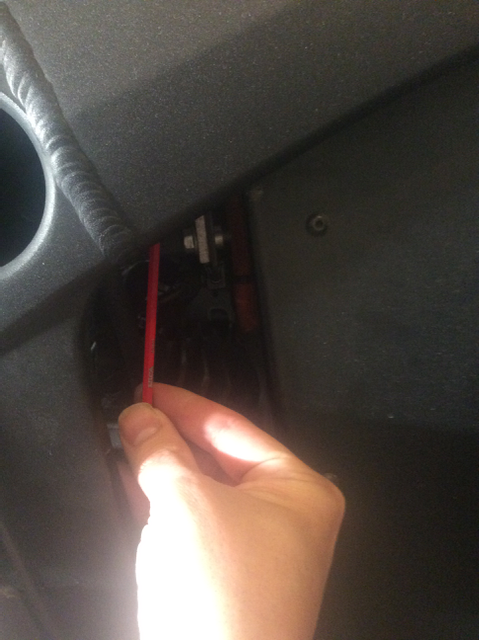 Lower right bolt |
 Lower right clip |
 Lower right clip |
| 7. Snip the cable run zip tie on the lower left corner of the plate. | |||
| 8. Snip the cable run zip tie on the lower edge of the plate from the right side. | |||
| - A long, narrow-bladed screwdriver can be suitable. | |||
| 9. Detach the Accessory Charging Port from the lower flange of the plate using a 2.5mm(?) Allen key on the two narrow bolts through the plug's body holes. | |||
| 10. Along the lower rear-facing edge bracket flange, push the cross-frame cable run off of the bracket. |
| | |
| --- | --- |
| { loading=lazy } *Board Plate Mounting Bracket (Left)* | { loading=lazy } *Board Plate Mounting Bracket (Right)* |
- Pull the top edge of the plate to the rear of the bike so that the top mounting flange's corners clear the mating flanges on the frame.
- Gently pull the plate by the DC-DC converter up and aft, minding any cabling that can get snagged on the plate to avoid straining any wires.
- It seems easiest to pull the left side of the plate up first, to avoid clearance issues around the hydraulic lines running along the right side towards the rear brake system.
Installation
- (Still working on this; essentially reversing the removal but considering the various fitment dependencies ahead of time to avoid trouble).
Tail Subassembly
On the SDS Platform models, there is a separate aluminum assembly supporting the tail plastics, tail extension for the license plate, and the top rack accessory that bolts into the "horns" at the aft end of the frame just after the Sevcon controller.
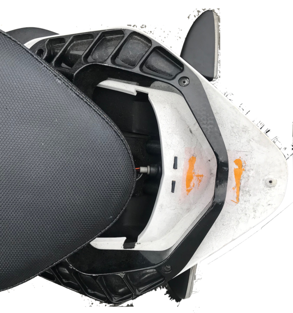 Zero S tail subframe with upper plastics removed
Tail Extension
The SDS Platform tail extension supports the license plate, turn signals, and reflectors at a distance from the underside of the tail.
Construction
The extension is made of two cast aluminum pieces, upper and lower, that fasten together.
Wiring
12V wiring runs through holes in the bracket's bolted mounting to the underside of the tail to each turn signal.
The barrel connector pins for the turn signals are part of the wiring inside the tail behind the seat.
12V wiring runs through the extension to the license plate support bracket to power a low level illuminator bulb.
Mounting
The tail extension bolts into the tail subframe using a pattern of 4 M5×15 bolts with washers.
The bolts fasten upwards into the tail subframe; use a 4mm Allen key wrench to remove or replace.
This bulb illuminates the license plate as required by law enforcement agencies.
It appears to be common across all Zero models and platforms, but do confirm and correct as needed.
Specification
This appears to be a T3.25 Wedge 12v (4-5w) bulb.
See 2016 Zero DS(R)/S(R) License Plate Light Bulb Spec. Info Requested
Kickstand
Zero's models' kickstands are made from cast aluminum and swings outward from the left side.
There is a safety interlock Hall sensor switch at the pivot that prevents the motor from operating when the kickstand is down.
| Years | Model | Length | Part no |
|---|---|---|---|
| 2013-2014? | S/SR | shorter than the DS/DSR | 20-05660 03 |
| 〃 | DS/DSR | 10.8" / 275mm | 20-05661 03 |
| 〃 | FX | 15.0" / 380mm | 20-05662 03 |
| 〃 | FXS | ||
| 2015+ | FX | 13.5" / 343mm | |
| 〃 | FXS | 11.8" / 300mm |
Both DS and FX kickstands are identical from the spring screw up to the pivot, and should interchange.
All the 2013+ kickstands uses the same pivot pin & spring.
References
Re: 2016 FXS Lowered Ride Height OEM Shock, Dual Use Tires, Drop Bars, Hand Guards,
Mounting
3/8" E clip, Zero part no 90-0283700, also available generically.
Clevis pin custom, Zero part no 90-0279900.
Mounting bracket, custom
Maintenance
The official manual recommends keeping the pivot greased as necessary with a six-month check interval.
Problems
A Loose Kickstand can result from inadequate greasing over time.
This replaces the Kickstand.
See Kickstand Removal and Kickstand Install for now.
Tools
- Center lift or stand.
- Large flat-blade screwdriver or specialized tool like drum brake spring pliers for spring removal and replacement.
- E-clip tool (or needlenose pliers) for the 3/8" E-clip.
Steps
- (When replacing) Remove the allen bolt securing the springs to the old kickstand.
- (When replacing) Transfer the 2 bronze bushings from the old kickstand:
- Remove the 2 bronze bushings from the old kickstand.
- Clean and grease bushings.
-
Insert bushings into new kickstand and replace chamfered bolt with springs.
My chamfered bolt was not very tight and I assume it was being held in from the spring tension.
I went to tighten it all the way in but that seemed to push the springs out too far.
I put blue Loctite on it and threaded it about half way in.
I will check this after a few rides to ensure it does not fall out! 3. Place the new kickstand onto the pivot. 4. Install the pin and spring
Pin Before Spring
- Insert the pin.
-
Raise the kickstand to its stowed/horizontal position.
This minimizes the amount of force/extension to install the new spring. 3. Install the spring over the kickstand hook with a suitable tool (see tools requirements).
Spring before pin
Have the pin and a tapered punch that fits nicely in the hole ready to go.
- Clean the pin and apply fresh grease to it.
- Hook the springs onto the frame, grip the kickstand with both hands, put your shoulder into the bike so it won’t tip.
- While pushing straight down on the kickstand, get it onto the frame and insert the tapered punch.
- Now raise the kickstand into the stowed/horizontal position.
-
Remove punch.
The hole will be almost aligned. 6. Insert the pin as far as it will go, mine stopped at the frame. 7. With the kickstand still in the up position, tap the bottom of the kickstand pivot area up towards the frame with a dead blow hammer while pushing the pin in.
This should align the hole and allow the pin to go right in.
Insert the pin and fasten it with a new 3/8" E-clip.
Note: This is the most difficult and dangerous part of the job.
Use eye protection while doing this and ensure your hands won't be damaged if the spring flies back while getting it over the hook.
Focus on applying steady force with as much leverage as possible to extend the spring back along the swingarm.
- One trick is to use a strong line looped through the hook as a pulley.
-
Another trick is to bend the spring enough back and forth to insert pennies between the coils, which holds it in an extended position.
Then loop the spring over the hook and pull the pennies out with pliers. 5. Check the operation of the kickstand a few times.
Ensure that it operates smoothly.
Ensure the kickstand sensor detects the position of the kickstand, by checking the interlock indication on the dash while the bike is keyed on. 6. Put the kickstand down before letting the motorcycle off the lift to rest on it.
Tools
- Center lift or stand.
- Large flat-blade screwdriver or specialized tool like drum brake spring pliers for spring removal and replacement.
- E-clip tool (or needlenose pliers) for the 3/8" E-clip.
Steps
- Place the motorcycle on a center lift or stand.
Spring Before Pin
- Pull the spring off of the kickstand hook with a large flat blade screwdriver or a specialized kickstand spring release tool.
Raise the kickstand to the stowed/horizontal position, to reduce spring tension.
 Warning: |
Be extremely careful working with the kickstand spring as it is under high tension. |
A specialized tool makes this easier. 2. Remove the pivot pin. 3. Remove the kickstand.
Pin Before Spring
- Remove the pivot pin.
- Pull the E-clip off of the inside of the pivot.
- Raise the kickstand to the stowed/horizontal position, to reduce spring tension.
- Go to the left side of bike.
- Wiggle the kickstand while tapping the pivot pin from underneath with for example a soft faced hammer.
-
Continue to wiggle the kickstand while gripping the pin until it slides out.
Often comes out by hand with a rag. 2. Carefully slide kickstand away from frame and unhook springs from frame.
The kickstand will still be under some tension from both springs, inner and outer.
Footpegs
Zero footpegs are cast aluminum pieces, mounted on identical hinges so are interchangeable across models.
Mounting
The mount bracket uses a custom clevis (10mm ⌀ with 40mm working length and 45mm overall length), secured with a retaining E-clip (3/8" or 9.5mm inner ⌀).
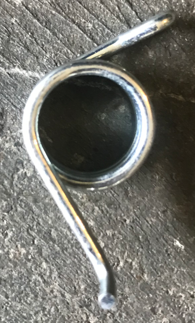
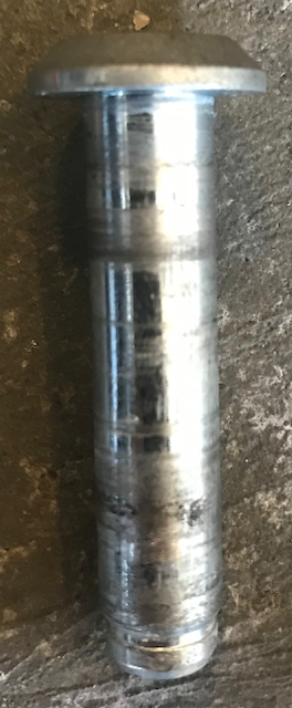
Repair
The footpegs' aluminum casting is relatively brittle, and the pegs tend to break rather than bend.
See Footpeg Replacement.
Reference
"Any pegs made for the 2008-2009 Suzuki RMZ450 should fit the DS,DSR,FX models"
Rider Footpegs
These Footpegs are only installed for the rider, versus Passenger Footpegs.
| Sport Footpegs Installed on S/SR/FXS models. Constructed as a cylindrical smooth-surfaced cast aluminum piece with a corrugated upper surface for some grip. They are spring-loaded. There is a hole at the end of the rider footpegs, with/for feeler stud measuring M6X16 with a DIN 1587 M6 18-8 cap/acorn nut. 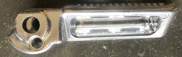 Sport Footpegs underside Dual Sport Footpegs Installed on DS/DSR/FX models. Constructed as a mildly-cleated rough-finish cast aluminum piece with a wide flat surface mounted horizontally. They are spring-loaded. Because of their construction, these actually offer less legroom than the sport footpegs. |
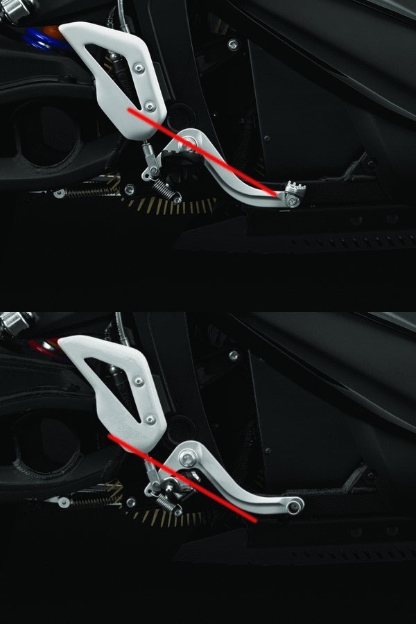 S and DS footpegs compared |
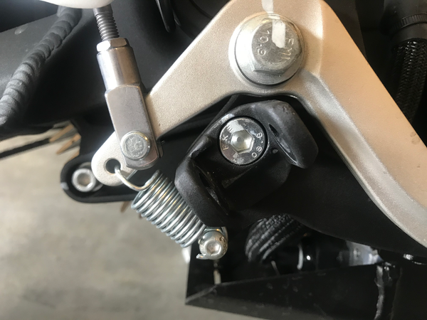 Rider footpegs mounting bracket
Rider Footpeg Removal
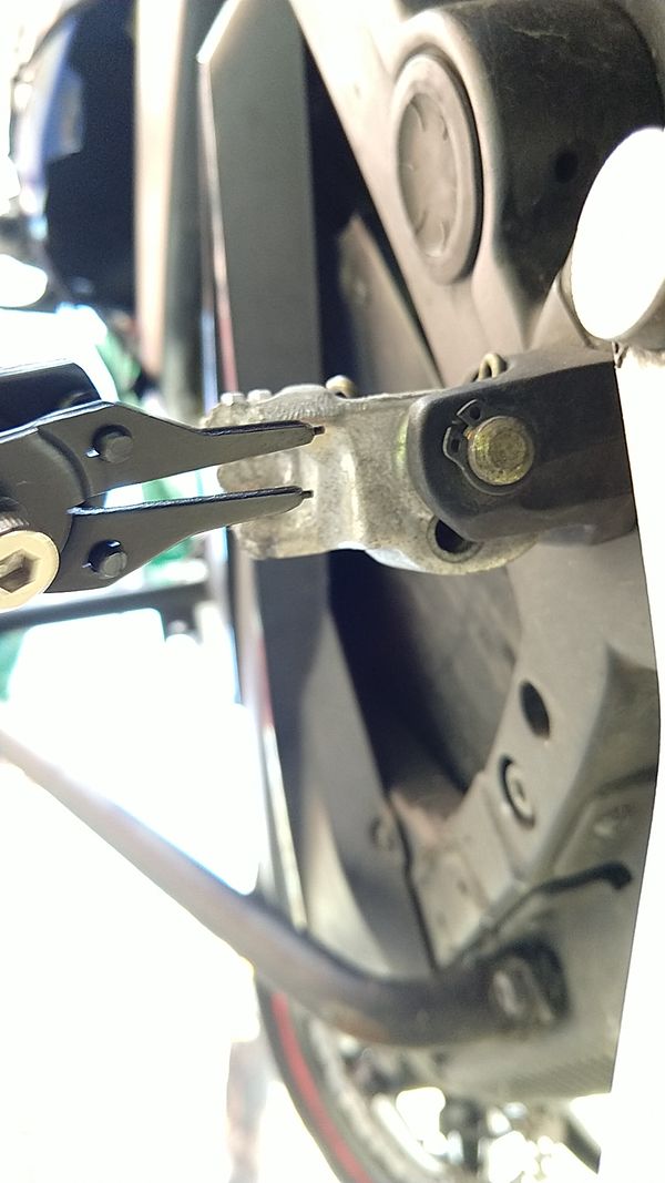 footpeg retaining clip and tool
Tools
- Snap Ring / E-Ring pliers (needlenose pliers are a common if less easy substitute).
- (Optional) 7mm Allen key to remove the clevis bracket from the frame.
Steps
- Gently spread the gap in the retaining E-ring using the pliers until it slides over the end of the pin, and remove it.
This clip is on the lower end of the footpeg retaining pin. 2. Pull the retaining pin up and out.
Hold and pull the pin spring and footpeg as the pin comes out. 3. (Optional) Use the 7mm Allen key to remove the bolt through the clevis bracket that fastens it to the frame.
References
How to Remove Zero Footpegs + Relocation Ideas by NewZeroLand on Youtube
Passenger Footpegs
Passenger footpegs are ergonomically identical to the sport rider footpegs, since passenger geometry requires reduced legroom and a forward foot angle on the rest.
They are not spring-loaded.
They lack the hole for the feeler stud that the rider footpegs use.
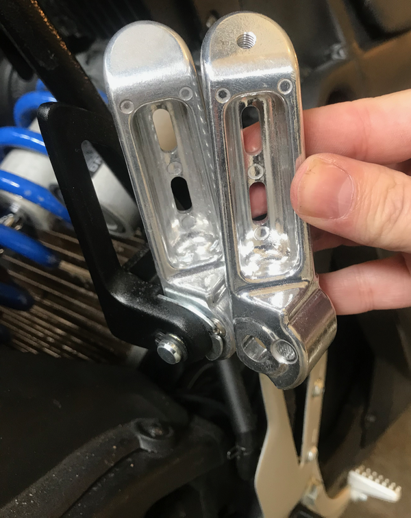 Sport Rider Footpegs vs Passenger Footpegs
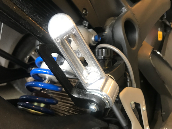 Passenger Footpegs Stowed
Mounting
The passenger footpegs hinge on the passenger footpeg bracket which mounts to the frame.
They use an additional installed pin and custom clip plate to secure the passenger pegs in either the stowed or out position (vertical and horizontal, respectively).
Passenger Footpeg Removal
footpeg retaining clip and tool
Tools
- Snap Ring / E-Ring pliers (needlenose pliers are a common if less easy substitute).
- 13mm hex side or socket wrench (for the bracket).
Steps
- Gently spread the gap in the retaining E-ring using the pliers until it slides over the end of the pin, and remove it.
This clip is on the lower end of the footpeg retaining pin. 2. Pull the retaining pin up and out.
Hold and pull the pin spring and footpeg as the pin comes out. 3. (Optional) Remove the bracket 1. Loosen the upper bolts mounting the footpeg brackets to the frame.
**S-platform:** Reaching these bolts from the rear is easiest since they are on the inside of the frame.
-
Loosen the lower bolts mounting the footpeg brackets to the frame.
S-platform: These face the motor and allow very low overhead.
A side wrench is recommended, and a ratcheting version preferred. 3. Remove the bolts and then the brackets.
References
How to Remove Zero Footpegs + Relocation Ideas by NewZeroLand on Youtube
Seat
Zero S Seat Pan
The S Platform seat is a proprietary design and fitment.
Seat retaining features
- A metal bracket with holes for retaining bolts that mount through the frame from the outside.
The bracket also serves to align the seat horizontally since the outer sides of the bracket must slide directly along the inside track of the frame.
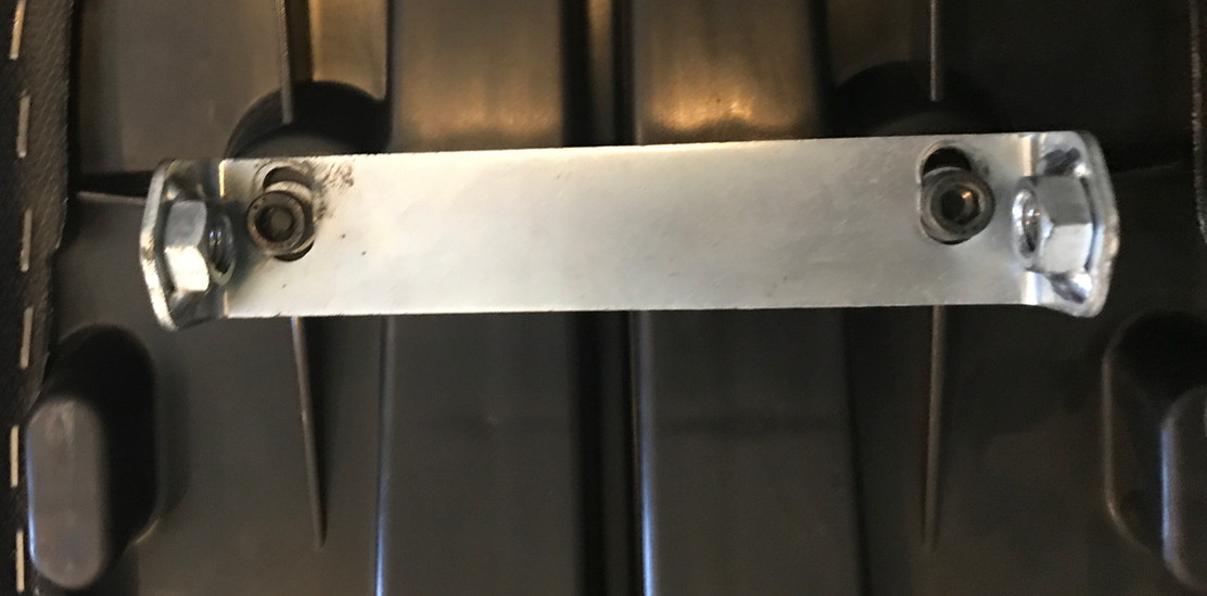

The bracket's part number is 20-0508307 and when separately ordered has been observed to have slotted holes to join to the seat for some adjustability. - In front and center, a pair of catches engages the frame's Y-shaped centerpiece under a pair of pins. - In front on the lowest outside edge, a pair of tabs point downwards that should slide inside the frame rails.
Without some care, these easily wind up outside the frame, flexing the seat pan and scuffing the frame lightly with plastic debris.
Under The Seat
2016 DSR tail layout
- The large controller dominates the space underneath the seat, on the lowest part of the tail structure.
There's no room around the controller for anything but its cabling and a conduit for tail lighting. - In front, the 12V fuse block is the main item to access.
There are cables between the battery and the controller; the MBB and DC-DC converter are beneath these cables. - Behind the controller is the tail wiring area which has a little room for a tire patch kit or some tools.
Of course, storing tools for removing the seat there is counter-productive.
Dimensions
- Seat
- Seat Bolts
M8 with 1.25mm thread, 50mm long with a round end for aligning the seat bracket with the frame.
With the top rack installed, the diameter of the hole around the head is slightly under 15mm, with a maximum offset of about 12mm. - Seat Bracket Bolts to Seat Pan
Seat Removal
This removes the seat from SDS Platform bikes.
Video Guide
Zero motorcycle - How to remove your seat by Alternative Standard on YouTube
Notes
- Unload any luggage racks before taking the seat off for an extended period of time to avoid stressing the racks.
When luggage racks are installed, the seat bolts are load bearing (or at least damping). - An M8-1.25×55mm socket cap bolt with a 6mm Allen head can be used if the kit bolt is lost.
Tools
- 2015+: T45 Torx wrench (for seat bolts).
- 2013-2014 (with top or side racks): 5mm Allen key (for seat bolts).
Steps
- When luggage racks are installed Remove the top case and/or side cases to ensure the rack is unloaded.
- Remove the M8-1.25×55 seat bolts.
Push the seat down and forward as needed to help ease out the bolts.
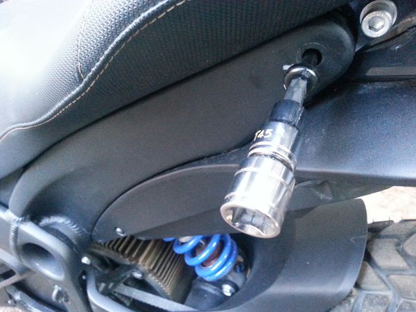 Seat Fasteners
 Seat Fasteners with Top Rack Installed
3. Pull the seat back a couple of inches and then upwards.
Seat Install
This installs the SDS Platform models' seat.
Tools
- 2015+: T45 Torx wrench (for seat bolts).
- 2013-2014 (with top or side racks): 5mm Allen key (for seat bolts).
Steps
- When luggage racks are installed Remove the top case and/or side cases to ensure the rack is unloaded.
- Place the seat on the tail slightly to the rear of where it will sit.
Ensure that the pan's horn-shaped catches will slip under the frame's Y-shaped centerpiece pins. 3. Push the seat forward and down to sit in place. 4. Visually align the holes of the seat bracket with the seat bolt holes.
Align the seat's bracket with the frame holes to avoid wear.
Align the seat's tabs between the frame rails to avoid stressing the seat pan and marring the frame.
If the top rack is installed, too, check the alignment of that as well to avoid wear trying to thread the bolts. 5. Insert the seat bolts, gently engaging while checking for cross-threading.
Check for alignment again while the bolt head encounters the seat bracket.
Press down and forward on the seat as needed to help align and tighten the bolts.
Seat Fasteners
Seat Fasteners with Top Rack Installed
6. Tighten the bolt head against the frame surface to hold it in place but do not over-tighten.
7. When luggage racks are installed Re-install the top case and/or side cases.
Panel Material
Gen2 body panels are made from ABS plastic.
2013-2016
The plastics' color is molded-in, and so it fades over time with sun exposure. On the other hand, they're relatively inexpensive to replace from Zero; ask your dealer.
Some use Plexus plastic cleaner to keep them polished successfully.
POLYTROL Colour restorer could help with color restoration.
Retr0bright solution developed for restoring 1980's yellowed ABS personal computer chassis material may be of use, unconfirmed.
2017+
The plastics as of this model year are painted rather than molded-in.
Tank Plastics
 2014 SP Tank Plastics (left)
 2014 SP Tank Plastics (right)
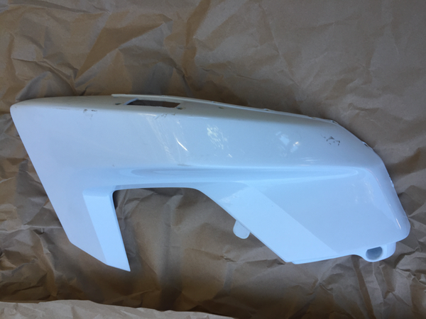
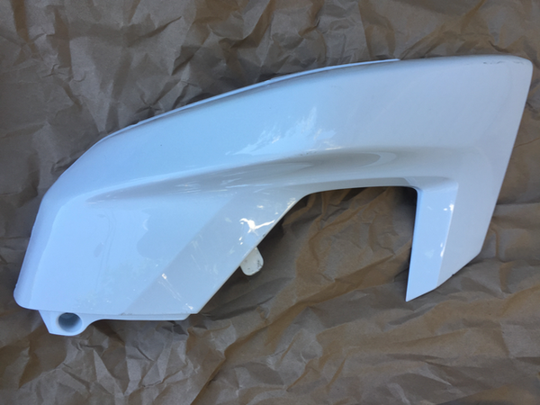
The 2013+ SDS Platform Frame features a "tank" area cradled by the two front frame spars and covered by plastic bodywork.
As delivered, it offers a storage compartment, but can also accommodate systems accessories like the OEM Power Tank battery upgrade or chargers.
All of the bodywork for this area serve the same ergonomic functions of a traditional motorcycle's fuel tank, allowing grip for maneuvering.
Fasteners
Zero plastics all are fastened with blackened M5x15mm mushroom cap socket head bolts using a 3mm allen key wrench.
All have black plastic washers with 5mm inner diameter, 10mm outer diameter, roughly 1mm thick.
Removal
Construction
All variants of the tank plastics for have identical side pieces and a black centerpiece in soft plastic with a relatively rough finish.
The stock centerpiece for 2013-2016 models is a bin container with two drain holes for collected moisture, with a soft bin held together with a simple zipper that anchors via hook-and-loop patches at the bottom of the bin as well as a loop cord that hooks through the front helmet lock.
The bin delivered per model year is different and varies in quality. 2013 seemed to have better construction than 2014-2015 years, and 2016 is somewhere between.
As of 2017, the stock centerpiece is a locking storage container with a spring-loaded hinge at the front so it swings forward to open.
The Power Tank and Charge Tank have tank plastic options which can be bought separately or selected for color customization. Both use a relatively flat surface for the centerpiece, and the Charge Tank has a cutout for a J1772 inlet hold with built in waterproof cover with a spring-loaded hinge.
 2014 SP plastics - dewelding
Separating
The join between the centerpiece and side pieces of a Zero tank plastic assembly is made by plastic weld using a soldering iron into soft hollow plastic pins on the centerpiece that melt and flatten around a lock washer onto holes in the side pieces.
You can break these welds using a relatively careful use of a pair of pliers to basically grip hard and twist on them until they break.
It's a slightly frustrating process but pretty quick to achieve, in about an hour. A soldering iron or extremely narrowly-focused heat gun can help the process but try not to risk damaging the plastics from overheating.
The original join process can be repeated for the new centerpiece.
Also, this means that the plastic centerpiece you remove will not be re-joinable.
Repair
See Tank Plastics Repair for a way to re-join tank plastics that have been de-welded.
Tail Plastics
The tail plastics on the SDS platform enclose the tail subframe and support the rear brake/running lights and the license plate holder with its turn signals.
Tail Plastics Removal
This removes the S-Platform Tail Plastics from the bike.
Note: The author documented the reassembly; removal was inferred. Confirmation would be helpful.
Zero S tail subframe with upper plastics removed
Video Guide
Zero motorcycle - How to remove your tail plastic by Alternative Standard on YouTube
Notes
You'll be disconnecting the rear lighting wiring and removing the tail subassembly, and then removing the tail plastics from that.
The lower plastics removal are particularly difficult, even for dealers!
Tools
- 3mm, 4mm, 6mm Allen wrenches.
- For the seat bolts: T45 Torx wrench (without top rack) or 5mm Allen wrench (with top rack).
- Phillips screwdrivers.
- Needle nose pliers.
Steps
- Remove the seat.
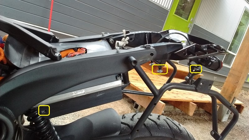
- Remove the black seat pan bolts and nylon washers with the 3mm Allen wrench
These are located lower on the side, near the hollow frame tube.
There are 5 pairs of bolts to remove (documented via reassembly analysis):
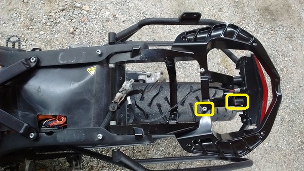 3. Use a Philips screwdriver to unscrew the bolt holding down the rear of the plastic controller cover.
4. Cut the cable ties around the signal wires on the left side of the seat area behind the controller.
5. Disconnect the turn signal wires and brake light / plate light wires.
Take a photo to record their connections for correct re-assembly.
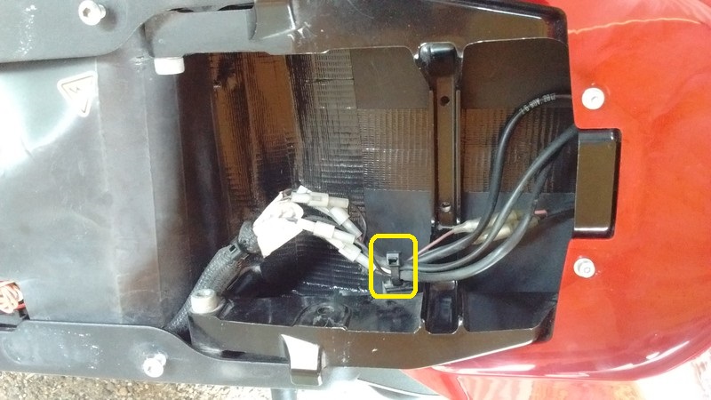
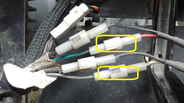 6. Remove the 4 bolts that hold tail frame with a 6mm Allen wrench.
This detaches the tail frame. 7. Remove the tail extension using a 4mm Allen wrench. Mind the turn signal wires that go through holes here; draw them through.
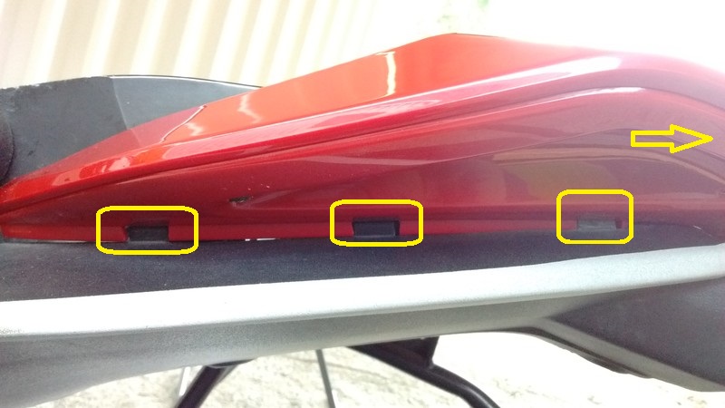
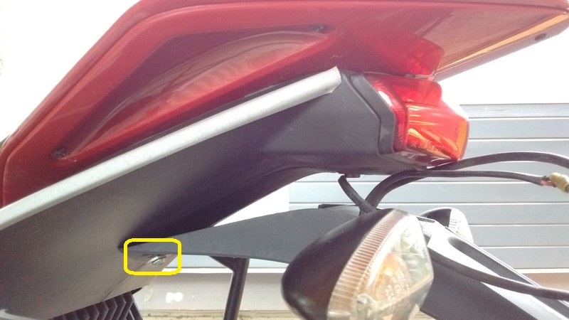 8. Remove the black tail enclosure plastics from the cosmetic plastics via the tabs.
There's also two clips at the end on top of the taillight.
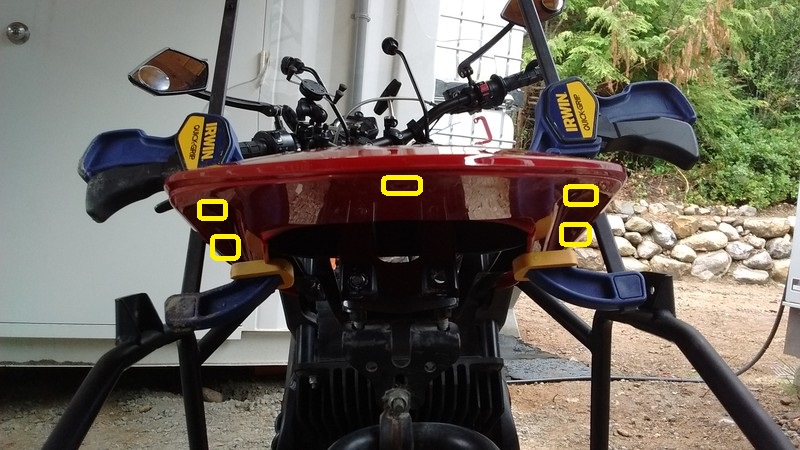
 9. Use a Philips screwdriver to remove 5 screws holding the cosmetic plastics to the frame from underneath.
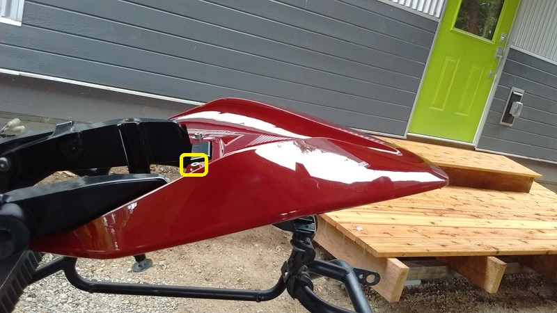
 10. Use a 3mm Allen wrench to remove the two screws holding the cosmetic plastics to the top of the frame.
{ loading=lazy }
Reassembly
- With the tail light off, bolt the top plastic to the metal frame.
 2. Clamp the bottom tail plastic and screw in the 5 screws that hold both pieces together
3. Here is how the black tail plastic fit with the tail light.
Notice the "zipper" down the middle.
There's also a very small one on top of the tail light.
On the outside are the tabs that clip into the cosmetic plastics.
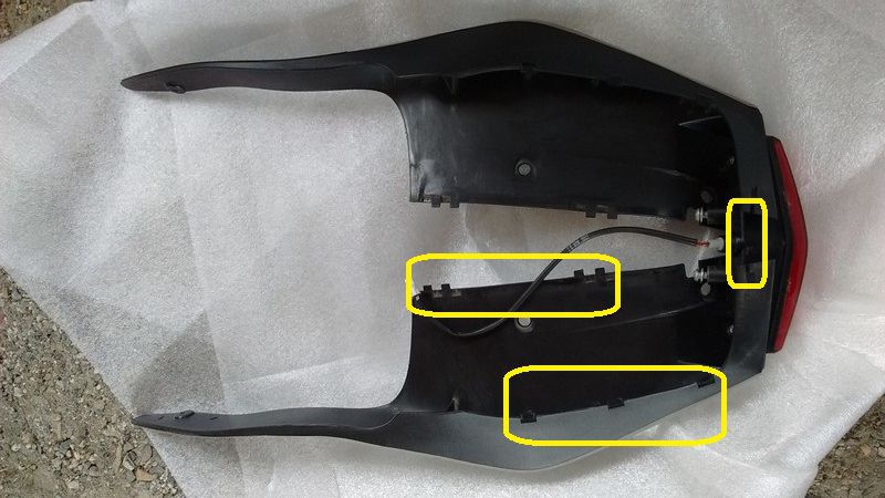
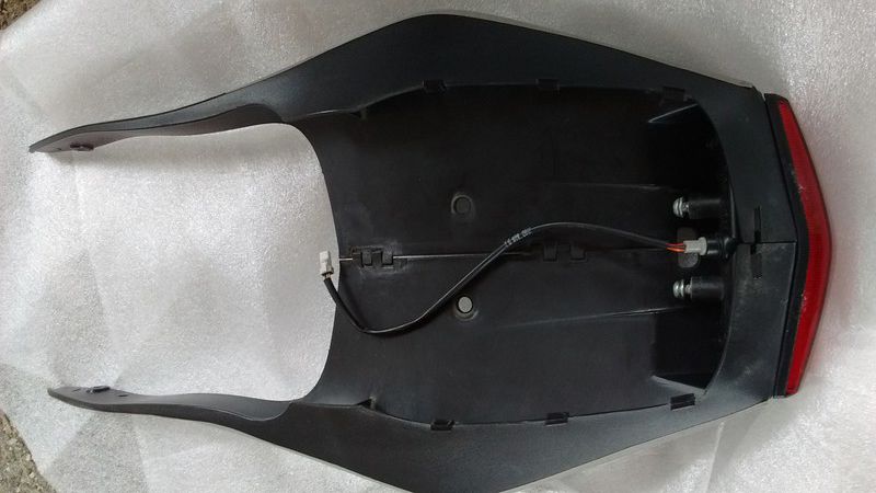 4. Loosely bolt the end of the black tail plastic to the frame.
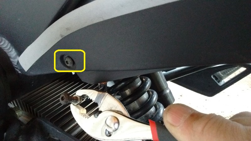
Note the small nut that's between two fins of the controller.
It can easily be held with a pair of pliers.
 5. Rotate the pieces up and temporarily (and loosely) attach them to the frame.
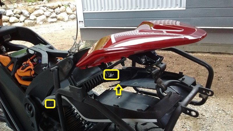
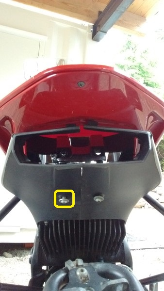 6. Bolt the tail light:
1. Remove the temporary bolts from the previous step.
2. Push a driver down through the plastic (because of the angle of the taillight bolts).
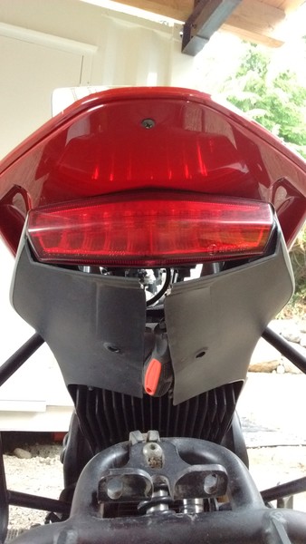
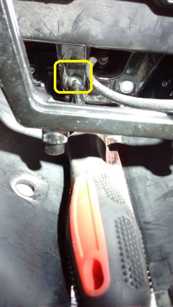 7. "Zip" the plastic back together.
There's also a tab on top of the tail light that must be fitted properly.
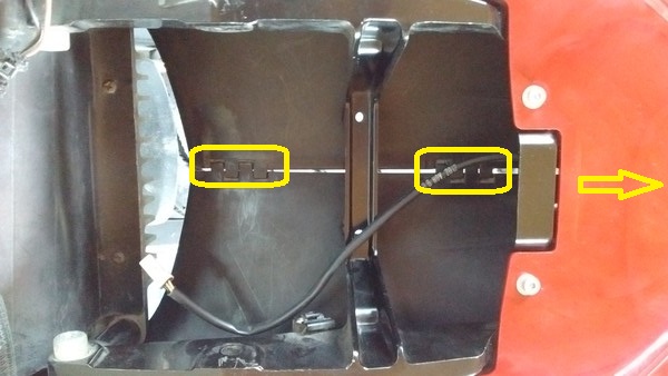
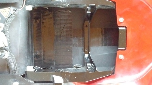
I added duck tape to seal the interior of the compartment to keep it cleaner.
 8. Snap the clips on the cosmetic plastic.
NOTE: It's not the cosmetic piece that should move but the black piece
I found it helped to have one hand inside and one hand outside to fit the pieces together.
There's also two clips at the end on top of the taillight.
9. Loosely bolt the tail and fit the wires back through the small hole.
10. Add a new zap strap and tidy things up.
{ loading=lazy } { loading=lazy }
Note that before disconnecting the wires, I took a picture of the set up to be able to match the colours.
In my case, red goes with green and white goes with grey (confirm locally). In the case of a 2018 SR, it was red/black to red and green/white to white.
-
Fasten all the loose bolts.
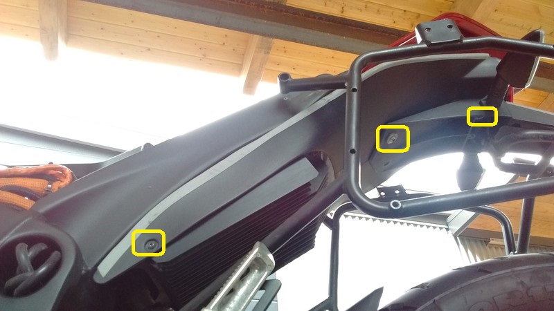 12. (If applicable) Re-attach the top and side racks.
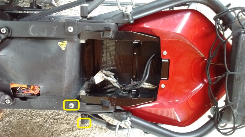
Lower Plastics
Lower plastics for the SDS Platform involve two side pieces to direct air towards the motor, and one in front to cover the battery.
There is some provision for guarding the battery compartment against an impact from the front wheel in the case of a collision.
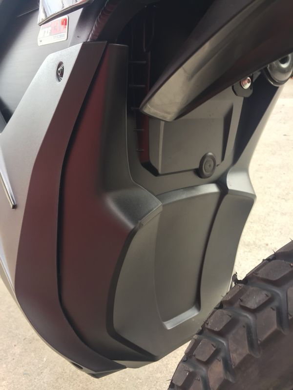 2017 Zero S Lower Front Plastics
2012-2013
Relatively angular and have their own bolt mount pattern.
2014+
Lower plastics have a sculpted re-design to deliver more airflow to the motor for cooling.
2017+
Single longbrick models (ZF6.5 and ZF7.2) have lower plastics with a latch and swinging hinge to access the storage area behind the half-size battery compartment.
Lower Plastics Removal
This removes the lower side panel plastics from 2012+ S platform models.
Tools
- 3mm Allen key
- (2012-2013) Ball-point pen or similar for plastic push rivets.
- (2019+) PH2 phillips head screwdriver for the front panel.
Steps
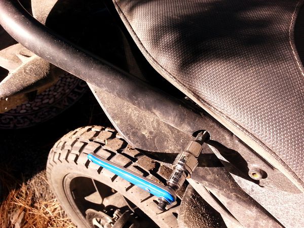
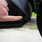
- Use the 3mm Allen key to remove the three M5 bolts holding each side panel: one at the top front corner, and one at each corner near the lower edge.
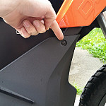 Top Front Corner bolt (2014+)
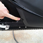 Lower Rear bolt (2014+)
 Lower Front bolt (2014+)
2. Remove each side panel.
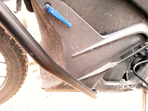 Removing the bolts
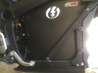 Side panel removed
3. (Optional) Remove the 2 bolts on each side holding the front panel on and remove it.
2012-2013: Use the ball-point pen or similar non-scratching pointed tool to push the center pin to release the plastic rivets on the front panel and remove it.
2013-2018: Use the 3mm Allen key
2019+: Use the PH2 Phillips head screwdriver to gently remove the plastic screws from the pop rivet, then pull the pop rivet out from the side slot.
References
Adapted from this forum post.
Source: zeromanual.com/wiki/SDS_Platform/Unofficial_Service_Manual · Wayback capture of 2025-05-17 · wiki last edited 10 July 2020 00:05. Community-written content from the Unofficial Zero Manual, reproduced for preservation; not written or verified by OpenZero. Links to pages that were not mirrored go to the Wayback Machine.